
Related Manuals for Danmeter CSM 2

Summary of Contents for Danmeter CSM 2
- Page 1 Cerebral State Monitor Model CSM 2 User Manual Danmeter A/S Kildemosevej 13, DK-5000 Odense C, Denmark Tel.: +45 63 11 29 30 Fax: +45 63 11 29 31 e-mail: info@danmeter.com www.danmeter.com Rx only...
-
Page 3: Table Of Contents
Table of Contents About this Manual ..........................1 Device description ........................1 Indications for Use........................1 List of Symbols ........................2 Installation and Preparation......................2 Skin Preparation and Sensor Positioning..................3 Description of the Device ........................4 General Overview ........................4 Keys and Controls Overview....................5 Light Indicators........................6 Description of Keys.........................6 Operation Display Modes......................7 Setup Menu..........................9 Settings..........................10... - Page 4 This manual is published by Danmeter A/S, who reserves the right to improve and modify the contents without prior notice. Modifications will, however, be published in future editions. All rights reserved. Cerebral State Monitor, CSM & CSI are trademarks of Danmeter A/S...
-
Page 5: About This Manual
This manual is intended to assist the user in operating the Cerebral State Monitor (CSM) in a safe and effective manner. This version of the manual was originally drafted, approved and supplied by Danmeter A/S in English. Before operating the monitor read this manual thoroughly, with particular attention to all warnings and cautions. -
Page 6: List Of Symbols
List of Symbols Type BF equipment On / Off Attention, consult accompanying documents Do not dispose of in refuse collection. Dispose of at a recycling station or equivalent in accordance with directive 2002-96-EC WEEE. Installation and Preparation The Cerebral State Monitor system CSM007 includes the following: Cerebral State Monitor CSM Wireless Link Patient Cable... -
Page 7: Skin Preparation And Sensor Positioning
Skin Preparation and Sensor Positioning To ensure low sensor impedance, clean skin with mild soap and water is recommended as a skin cleanser. Note: Alcohol is not recommended as a skin cleanser; it leaves a film layer that may cause high sensor impedance. -
Page 8: Description Of The Device
Description of the Device General Overview On/Off Patient cable power/charge connection connection Battery Battery lid compartment Cerebral State Monitor - CSM DFU Page 4... -
Page 9: Keys And Controls Overview
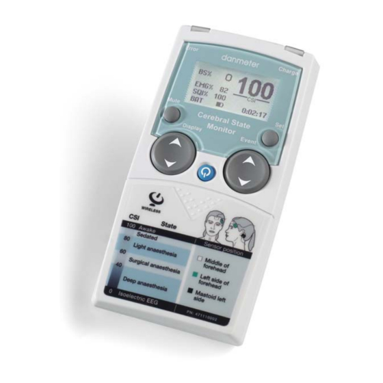
Keys and Controls Overview RED Error GREEN Power light adapter Charge Error On/Off Display area Mute Mute Set Event Display Event Display Event Type Control Cerebral State Monitor - CSM DFU Page 5... -
Page 10: Light Indicators
Light Indicators 2 RED Error light Lights up when neuro sensor error situations are detected 3 Lights when power adapter is connected Description of Keys 1 Power On Press once 1 Power Off Press and hold until “Power Off” bar disappears 1 Wireless Link connection, disconnection or reconnection Press twice within 1 second 5 Mute key Mutes alarms... -
Page 11: Operation Display Modes
Operation Display Modes The CSM always starts with display A Switch between display A, B, C, D and E by pressing the Display key (7). Display Mode D CSI trend histogram with 5-minute interval showing average, lowest and highest CSI values within the interval. EMG% is displayed as a bar in the right panel Display Mode C CSI trend curve with event markers and BS curve. - Page 12 The EEG waveform derives from the signal recorded between the frontal and mastoid electrodes. The frequency content is 2-35 Hz. If the EEG amplitude is low then in some conditions the ECG might be detectable in the EEG waveform EMG% is shown in the display as a bar in the right-hand side. Operating time and numerical value for current CSI and BS%.
-
Page 13: Setup Menu
Setup Menu General menu structure and menu selections Top Menu BS% 0 47 CSI Menu Alarm Config Device information How to select menu settings from Display Mode Remove battery lid. From any Display Mode, press any arrow on the Control key (9). The top menu appears. -
Page 14: Settings
Settings Parameter Menu Description Values (Default) High Alarm Alarm Selects the CSI Alarm High Option ON/OFF (OFF) Low Alarm Alarm Selects the CSI Alarm Low Option ON/OFF (OFF) High Limit Alarm Selects the CSI High Alarm Level 2-99 (60) Low Limit Alarm Selects the CSI Low Alarm Level 1-98... -
Page 15: Events
Device Information: Select submenu. BS% 0 47 CSI Device information Info Link Info: • Serial number. • SW version. • CSI version. • AD version. Link: • - indicates no CSM Link connected. • If CSM Link connected the CSM Link serial number and software version will be shown. Log: •... -
Page 16: Csm Parameters
CSM Parameters BS% Indicator The amount of Burst Suppression (very low-amplitude or “flat” EEG) is displayed in all Display Modes at the top left hand side. Please refer to Section 5.5 for further information on the BS% measurement. EMG% and EMG bar The EMG level is displayed either as a numerical percentage (0-100%) value in Display Mode A or graphically as a bar at the right hand side in Display Mode B. - Page 17 Battery Symbol An icon labelled “BAT” in Display Mode A indicates the remaining battery capacity. For further information on battery operation of the CSM, please see section 6. Battery about 50-percent charged Battery charging when icon animates Battery fully charged (if not animated) Note: ONLY CSM Battery (CSMX04) will be charged in CSM Monitor LINK Signal Symbol...
-
Page 18: Principle Of Operation
Principle of Operation High Quality Amplifier An instrumentation amplifier collects ongoing EEG with a high Common Mode Rejection Ratio ensuring a high-quality EEG acquisition. Special artifact detection algorithms are used to eliminate their effects on subsequent CSI calculations. Measurement Principle The performance of the CSM is based on the analysis of the frequency content of the EEG signal. -
Page 19: Csi Scale
CSI Scale The CSI is a unit-less scale from 0 to 100, where 0 indicates a flat EEG and 100 indicates EEG activity corresponding to the awake state. The range of adequate anesthesia is designed to be between 40 and 60. All values in the table are approximate values based on the mean values of the patient behaviour. -
Page 20: Emg
High levels of facial muscular or electromyographic (EMG) activity can interfere with the CSI under certain circumstances. The monitor incorporates an EMG filter that removes most of the potential interfering EMG activity. The EMG bar shows the energy of the EMG level in the 75–85 Hz frequency band (0–100 logarithmic). -
Page 21: Csm Battery / Csm Power Operation
CSM Battery / CSM Power Operation Using CSM Power and CSM Rechargeable Batteries The CSM can be operated in two different modes • Battery operated • CSM Power operated Warning: Only standard CSM rechargeable battery CSMX04 or alkaline batteries must be used. Battery operation (Alkaline batteries) •... - Page 22 CSM Power Connect to power cable Connect to CSM Power connection Insert the CSM rechargeable battery as indicated Connect power cable to outlet and turn on power Green indicator (3) lights up Turn on monitor When the CSM is connected to an electrical outlet, and turned on, the CSM can be operated while the CSM battery is charged.
-
Page 23: Data Recording Via Csm Link
Data Recording via CSM Link CSM Link Software The real-time data capturing software for the Cerebral State Monitor makes it possible to record online data wireless via the CSM Link. The following data is recorded: • • • • Sensor impedance •... - Page 24 Connecting CSM Monitor and CSM Link Turn on the CSM Link. Power indicator shows a constant light. Link indicator is off. Turn on the CSM monitor. The CSM monitor shows a list of CSM Links found. Select CSM Link ID (Serial No.) with the Event key (8) and the indicator Link flashes, or choose skip in order not to establish a connection.
-
Page 25: Specifications
4.6 ounces 130 g) with battery Dimensions 4.6x2.7x1.2” Classification Internal power supply/ Class II, type BF, continuous use Sensors Danmeter Neuro Sensors Cable length 77” with 14” split Mounting options Velcro strip 1.7x0.9” Memory Data recording 18 hours Environment – Operation Temperature 50–104°F... -
Page 26: Accessories
Accessories CSMX04 CSM rechargeable battery CSMX05 CSM Power/Charger CSMX06 Patient cable CSMX09 Carrying case CSMX10 Service manual, English CSMX11 CSM Link Software CSMX12 CSM Link RS232 CSMX19 CSM Link USB CSMX18 CSM Link PHILIPS VOI CSMX13 Velcro Strip (1.7x0.9”) DMX004 RS-232 cable DMX013 USB cable... - Page 27 Cleaning Clean the monitor periodically by wiping the outer case with a lint-free cloth lightly moistened with warm water and a mild, non-abrasive cleaning solution or 70% isopropyl alcohol. Note The monitor case is resistant to the following cleaning solutions: •...
-
Page 28: Troubleshooting
11 Troubleshooting • CSM does not turn on when power key is pressed? Change to a new battery or a fully recharged battery. If changing the battery does not help, send the CSM for service. • Rechargeable Battery seems to have a diminished user time 1. - Page 29 • CSI is higher than expected Check anesthetic delivery systems: IV lines and status of vaporizers. Some patients require a higher dose of drugs due to interpatient variability. Adequate dosing for maintenance may not be sufficient for increased stimulation. • CSI rises along with EMG High levels of facial muscular or electromyographic (EMG) activity can elevate the CSI under certain circumstances.
-
Page 30: System And Error Messages
12 System and Error Messages For error codes (1-10 and 14) shown in the display, contact the appropriate service or distribution center. See section 14. Together with the error code an audible alarm is activated. Error codes 11, 12 and 13 can occur if the patient cable or the electrodes are connected while the CSM is performing the start up check. - Page 31 Accessories are free from defects in material and workmanship under normal use and service for a period of ninety (90) days from the date of delivery by Danmeter to the first purchaser. If any product requires service during the applicable warranty period, the purchaser should communicate directly with the local Danmeter service center to determine the appropriate repair facility.
-
Page 32: Service And Contacts
This warranty is in lieu of all other warranties, expressed or implied, and of all other obligations or liabilities of Danmeter, and Danmeter does not give or grant, directly or indirectly, the authority to any representative or other person to assume on behalf of Danmeter any other liability in connection with the sale of Danmeter products. - Page 33 Notes Cerebral State Monitor - CSM DFU Page 29...
-
Page 34: Technical Description
Technical description Guidance and manufacturer’s declaration — electromagnetic emissions The Cerebral State Monitor CSM is intended for use in the electromagnetic environment specified below. The customer or the user of the CSM should assure that it is used in such an environment. Electromagnetic environment —... - Page 35 typical commercial or hospital environment. ±2 kV common mode Voltage dips, short <5% Not Applicable Power quality should interruptions and be that of a typical (>95 % dip in voltage variations on commercial or hospital for 0.5 cycles power supply lines environment.
- Page 36 Recommended separation distance Conducted RF 3 Vrms 3 Vrms IEC / EN 61000- 150kHz to 80 3 V/m 80 MHz to 800 Radiated RF 3 V/m IEC / EN 61000- 80 MHz to 2,5 800 MHz to 2,5 GHz where is the maximum output power rating of the transmitter in watts (W) according to the...
- Page 37 Field strengths from fixed transmitters, such as base stations for radio (cellular/cordless) telephones and land mobile radios, amateur radio, AM and FM radio broadcast and TV broadcast cannot be predicted theoretically with accuracy. To assess the electromagnetic environment due to fixed RF transmitters, an electromagnetic site survey should be considered. If the measured field strength in the location in which the CSM Is used exceeds the applicable RF compliance level above, the CSM should be observed to verify normal operation, If abnormal performance is observed, additional measures may be necessary, such as reorienting or...
Need help?
Do you have a question about the CSM 2 and is the answer not in the manual?
Questions and answers