Advertisement
Quick Links
LOW PRESSURE
PORT
HIGH PRESSURE
PORT
MOUNTING HOLES
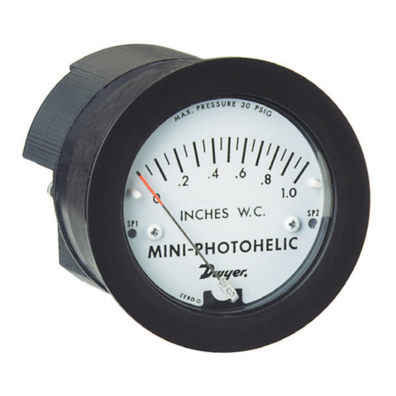
The Series MP Mini-Photohelic differential pres-
sure switch/gage combines the time proven Minihelic
II
®
differential pressure gage with two SPDT switching
setpoints. The Mini-Photohelic is designed to mea-
sure and control positive, negative, or differential pres-
sures consisting of non-combustible and non-corro-
sive gases. Gage reading is independent of switch
operation. Switching status is visible by LED indica-
tors located on the front and rear of the gage.
DWYER INSTRUMENTS, INC.
P.O. BOX 373 • MICHIGAN CITY, INDIANA 46361, U.S.A.
Series MP Mini-Photohelic
Differential Pressure Switch/Gage
Specifications - Installation and Operating Instructions
–
Ø2-19/32
[65.88]
+
1 [25.4]
3-1/32 [77.00]
3-1/8 [79.38]
9/32 [7.14]
3-7/8 [98.43]
SPECIFICATIONS
GAGE SPECIFICATIONS
Service: Air and non-combustible, compatible gases.
Wetted Materials: Consult factory.
Accuracy: +/- 5% of full scale @ 70°F (21.1°C). Gage
face mounted in vertical position.
Pressure Limits: 30 psig (2.067 bar).
Temperature Limits: 20 to 120ºF (-6.7 to 49°C).
Process Connections: Barbed for 3/16˝ I.D. tubing
(STD); 1/8˝ male NPT (optional).
Size: 4-1/8˝ (104.78 mm) depth x 3-1/16˝ (77.79 mm)
diameter.
Weight: 23 oz (652 g).
SWITCH SPECIFICATIONS
Switch Type: (2) SPDT relays.
Electrical Rating: 5A @ 120/240 VAC Resistive; 5A @
30 VDC.
Electrical Connections: Screw Type Terminal Block.
Accepts 22-12 AWG wire.
Power Requirements: 24 VDC / 24 VAC 50/60 Hz 4
watts.
Mounting Orientation: Gage face in vertical position.
Set Point Adjustment: Push Buttons.
Standard Accessories: (2) mounting screws, (1) .050˝
hex allen wrench.
Agency Approvals: UL, cUL.
Phone: 219/879-8000
Fax: 219/872-9057
Bulletin B-37
Ø3-1/16 [77.79]
www.dwyer-inst.com
e-mail: info@dwyer-inst.com
Advertisement

Related Manuals for Dwyer Instruments MP Mini-Photohelic Series


Summary of Contents for Dwyer Instruments MP Mini-Photohelic Series
- Page 1 Standard Accessories: (2) mounting screws, (1) .050˝ hex allen wrench. Agency Approvals: UL, cUL. DWYER INSTRUMENTS, INC. Phone: 219/879-8000 www.dwyer-inst.com P.O. BOX 373 • MICHIGAN CITY, INDIANA 46361, U.S.A. Fax: 219/872-9057...
- Page 2 INSTALLATION 4. Zeroing: Before installation, the Mini-Photohelic may 1. Location: Select a location free from excessive need to be zeroed before placing into operation. If zero- vibration and where ambient temperature will be between ing is required, you must first remove the locking clip 20 to 120ºF (-6.7 to 49ºC).
- Page 3 6. Electrical Connections: Refer to Fig. C for electrical 8. Circuit Style: The Mini-Photohelic is available with sev- connections located on rear on Mini-Photohelic: eral factory installed optional circuits. They are identified S1 → SP1 Reset Terminal (Do not apply power) by the label shown in Fig.
- Page 4 S2. The right setpoint relay SP2 would thus be reset and the cycle could repeat. ©Copyright 2003 Dwyer Instruments, Inc. Printed in U.S.A. 5/03 FR# 14-443249-00 Rev. 1 DWYER INSTRUMENTS, INC.
Need help?
Do you have a question about the MP Mini-Photohelic Series and is the answer not in the manual?
Questions and answers