Advertisement
Table of Contents
Advertisement
Table of Contents

Related Manuals for Evotech Yamaha MT-09 Tail Tidy


Summary of Contents for Evotech Yamaha MT-09 Tail Tidy
- Page 1 Yamaha MT-09 Tail Tidy Installation Instructions...
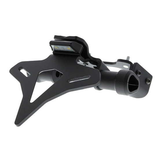
- Page 2 Installation Instructions Kit Contents PRN013753 1 x Main Bracket 2 x M5 x 20 Button Head Bolt 1 x Lower Bracket 2 x O-Rings 1 x Main Tail Tidy 2 x Vinyl Caps 1 x Upper Tail Tidy 2 x Indicator Retainer 1 x Axle Block R/H 2 x Indicator Extensions 2 x M4 Nuts...
- Page 3 Installation Instructions...
- Page 4 Installation Instructions...
- Page 5 Installation Instructions...
- Page 6 Installation Instructions...
- Page 7 Installation Instructions Reverse Stages 3 - 1...
- Page 8 Installation Instructions...
- Page 9 Installation Instructions...
- Page 10 Installation Instructions...
- Page 11 Installation Instructions...
- Page 12 Installation Instructions...
- Page 13 Installation Instructions Installation Instructions...
- Page 14 Installation Instructions...
- Page 15 Installation Instructions...
- Page 16 Installation Instructions...
- Page 17 Installation Instructions...
- Page 18 Installation Instructions Torque 108ft lb Torque 147N m...
- Page 19 Installation Instructions...
- Page 20 Installation Instructions...
- Page 21 Installation Instructions...
- Page 22 Installation Instructions...
- Page 23 Installation Instructions...
- Page 24 Installation Instructions Repeat Both Sides...
- Page 25 Installation Instructions...
- Page 26 Installation Instructions...
- Page 27 Installation Instructions...
- Page 28 Installation Instructions...
- Page 29 Installation Instructions...
- Page 30 Installation Instructions...
- Page 31 Installation Instructions...
- Page 32 Installation Instructions...
- Page 33 Installation Instructions...
- Page 34 Installation Instructions...
- Page 35 Installation Instructions...
- Page 36 Installation Instructions...
- Page 37 Installation Instructions...
- Page 38 Installation Instructions...
- Page 39 Installation Instructions Repeat For Both O-rings...
- Page 40 Installation Instructions Repeat For Both Indicators...
- Page 41 Installation Instructions...
- Page 42 Installation Instructions...
- Page 43 Installation Instructions...
- Page 44 Installation Instructions Ensure indicators are installed on the correct sides - drain Caution holes should face down...
- Page 45 Installation Instructions Repeat Both Sides...
- Page 46 Installation Instructions Run wires neatly down the channel in both parts ensuring they Caution do not get trapped or squashed...
- Page 47 Installation Instructions...
- Page 48 Installation Instructions...
- Page 49 Installation Instructions...
- Page 50 Installation Instructions OEM PART OEM PART...
- Page 51 Installation Instructions...
- Page 52 Installation Instructions Run wires neatly down the channel in both parts ensuring they Caution do not get trapped or squashed...
- Page 53 Installation Instructions Repeat Both Sides...
- Page 54 Installation Instructions Repeat OEM PART OEM PART Both Sides...
- Page 55 Installation Instructions Remove Clamp Re t Bolt...
- Page 56 Installation Instructions...
- Page 57 Installation Instructions...
- Page 58 Installation Instructions...
- Page 59 Installation Instructions...
- Page 60 Installation Instructions...
- Page 61 Installation Instructions...
- Page 62 Installation Instructions Pull Wire Through...
- Page 63 Installation Instructions...
- Page 64 Installation Instructions...
- Page 65 Installation Instructions Reverse Stages 24 - 18...
- Page 66 Re ector Bracket Installation...
- Page 67 Number Plate Adaptor Installation Instructions...
Need help?
Do you have a question about the Yamaha MT-09 Tail Tidy and is the answer not in the manual?
Questions and answers