Table of Contents
Advertisement
Quick Links
Description
Demonstration circuit 2053A is a dual-output, high ef-
ficiency, high density, µModule
from a 4.5V to 17V input range. Each output can supply
9A maximum load current. The demo board features the
LTM4675 a dual 9A or single 18A step-down regulator
with PMBus digital power system management. Please see
the
LTM
4675
data sheet for more detailed information.
®
The DC2053A powers up and regulates its outputs accord-
ing to the LTM4675's factory-default EEPROM settings.
Configuration resistors pin-straps can set device switch-
ing frequency and output voltage, if desired. Serial bus
communication is not needed to configure or evaluate the
LTM4675, facilitating quick set up and easy lab evaluation
of the DC/DC converter. To fully explore the extensive DPSM
features of the part, install the GUI software LTpowerPlay™
onto your PC and use LTC's I
BoarD photo
Dual Step-Down µModule Regulator
with PMBus Power System Management
regulator, operating
®
2
C/SMBus/PMBus dongle
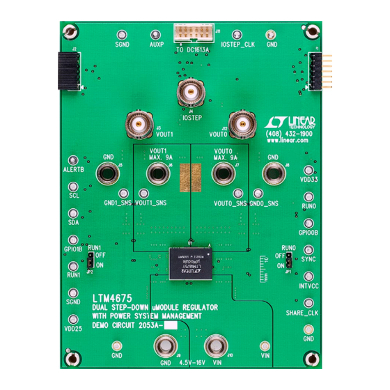
Figure 1. Dual-Output LTM4675/DC2053A Demo Circuit
DEMO MANUAL DC2053A
DC1613A to connect to the board. LTpowerPlay allows
the user to reconfigure the part on the fly and store the
configuration in the module's EEPROM, view telemetry of
voltage, current, temperature and fault status, and more.
GUI Download
The software can be downloaded from:
http://www.linear.com/ltpowerplay
For more details and instructions on LTpowerPlay, please
refer to the LTpowerPlay GUI for LTM4675 Quick Start
Guide.
Design files for this circuit board are available at
http://www.linear.com/demo/DC2053A
L, LT, LTC, LTM, Linear Technology, µModule and the Linear logo are registered trademarks
and LTpowerPlay is a trademark of Linear Technology Corporation. All other trademarks are the
property of their respective owners.
LTM4675EY
dc2053afa
1
Advertisement
Table of Contents

Related Manuals for Linear DC2053A


Summary of Contents for Linear DC2053A
- Page 1 DC/DC converter. To fully explore the extensive DPSM features of the part, install the GUI software LTpowerPlay™ L, LT, LTC, LTM, Linear Technology, µModule and the Linear logo are registered trademarks and LTpowerPlay is a trademark of Linear Technology Corporation. All other trademarks are the onto your PC and use LTC’s I...
-
Page 2: Performance Summary
(+) lead. OUT1 (Initial load: no load). Connecting a PC to DC2053A 4. Connect the DVMs to the input and outputs. Set default jumper position: JP1: ON; JP2: ON. You can use a LTpowerPlay on a PC to reconfigure the power management features of the LTM4675 such as: 5. - Page 3 DEMO MANUAL DC2053A Quick start proceDure Figure 2. Proper Measurement Equipment Setup – Figure 3. Measuring Output Voltage Ripple dc2053afa...
- Page 4 DEMO MANUAL DC2053A Quick start proceDure Figure 4. Demo Setup with PC = 3.3V, 650kHz = 2.5V, 650kHz = 1.8V, 650kHz = 1.5V, 575kHz = 1.2V, 500kHz = 1V, 500kHz = 0.9V, 425kHz LOAD CURRENT (A) DC2053a F05 Figure 5. Efficiency vs Load Current at V...
- Page 5 DEMO MANUAL DC2053A Quick start proceDure = 5V, 1MHz = 3.3V, 650kHz = 2.5V, 650kHz = 1.8V, 650kHz = 1.5V, 575kHz = 1.2V, 500kHz = 1V, 500kHz = 0.9V, 425kHz LOAD CURRENT (A) DC2053a F06 Figure 6. Efficiency vs Load Current at V...
- Page 6 DEMO MANUAL DC2053A Quick start proceDure OUT1 20MHz BW 20mV/DIV 4A TO 9A LOAD STEP DC2053a F08 Figure 8. Output Voltage V vs Load Current (V RANGE = 0) OUT1 OUT1 OUT0 20MHz BW 10mV/DIV DC2053a F09 Figure 9. Output Voltage Ripple at V...
- Page 7 DEMO MANUAL DC2053A Quick start proceDure OUT1 20MHz BW 20mV/DIV DC2053a F10 Figure 10. Output Voltage Ripple at V = 12V, V = 1.8V, I = 9A OUT0 OUT0 Figure 11. Thermal Performance at V = 12V, V = 1V, I...
-
Page 8: Ltpowerplay Software Gui
You can use LTpowerPlay to an automatic update feature to keep the software current evaluate Linear Technology ICs by connecting to a demo with the latest set of device drivers and documentation. board system. LTpowerPlay can also be used in an offline... - Page 9 1. Download and install the LTpowerPlay GUI: http://linear.com/ltpowerplay 2. Launch the LTpowerPlay GUI. a. The GUI should automatically identify the DC2053A. The system tree on the left hand side should look like this: b. A green message box shows for a few seconds in...
-
Page 10: Parts List
DEMO MANUAL DC2053A parts List ITEM REFERENCE PART DESCRIPTION MANUFACTURER/PART NUMBER Required Circuit Components CIN1 CAP, 150µF, 35V, ALUMINUM ELECTR, SUN ELECT, 35CE150AX CIN2, CIN4 CAP, X5R, 10µF, 35V, 10%,1210 MURATA, GRM32ER6YA106KA12 COUT1 TO COUT3, COUT6 TO COUT8 CAP, X5R, 100µF, 6.3V, 20% 1210... -
Page 11: Schematic Diagram
DEMO MANUAL DC2053A schematic DiaGram dc2053afa... - Page 12 DEMO MANUAL DC2053A schematic DiaGram dc2053afa...
- Page 13 Information furnished by Linear Technology Corporation is believed to be accurate and reliable. However, no responsibility is assumed for its use. Linear Technology Corporation makes no representa- tion that the interconnection of its circuits as described herein will not infringe on existing patent rights.
- Page 14 Linear Technology Corporation (LTC) provides the enclosed product(s) under the following AS IS conditions: This demonstration board (DEMO BOARD) kit being sold or provided by Linear Technology is intended for use for ENGINEERING DEVELOPMENT OR EVALUATION PURPOSES ONLY and is not provided by LTC for commercial use. As such, the DEMO BOARD herein may not be complete in terms of required design-, marketing-, and/or manufacturing-related protective considerations, including but not limited to product safety measures typically found in finished commercial goods.
Need help?
Do you have a question about the DC2053A and is the answer not in the manual?
Questions and answers