Advertisement
Description
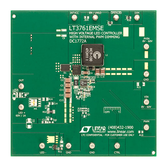
DC1772A is a high voltage LED controller with internal
PWM dimming. It generates its own PWMOUT waveform
for accurate PWM dimming with up to 25:1 brightness
ratio. It accepts an input voltage from 8V to 60V (8V UVLO
and 9.1V rising turn-on), and drives up to 60V of LEDs
at 1A (when PVIN is less than V
both PWM and analog dimming of the LED string. It has
an OPENLED flag that indicates when the LED string has
been removed.
DC1772A features high efficiency at 350kHz switching
frequency. At high LED string voltages up to 60V and
1A of LED current, the single switch controller has 94%
efficiency. The open LED overvoltage protection uses
the IC's constant voltage regulation loop to regulate the
output to approximately 69.8V if the LED string is opened
although it may reach 74V peak during transient from
running LEDs to open. The maximum LED string voltage
can be raised from 60V to 65V (or higher) with a simple
change of feedback resistors.
For low input voltage operation, the CTRL pin voltage is
reduced as the input voltage drops below 10V, reducing
LED brightness and restraining the peak switch currents
in order to limit inductor and switch size. UVLO turns the
LEDs off when PVIN drops below 8V.
DC1772A PWM dimming is simplified when compared
with other LED drivers. The LT
PWMOUT dimming waveform at a frequency determined
). DC1772A features
LED
3761 generates its own
®
DEMO MANUAL DC1772A
High Voltage LED Controller
with Internal PWM Dimming
by the capacitance on the PWM pin (C8 gives 300Hz for
DC1772A). The PWMOUT duty cycle is determined by the
voltage on the DIM terminal. Between 0V and 7.7V VDIM
gives between 4% and 96% PWM duty cycle. Information
regarding PWM dimming ratios and performance can be
found in the LT3761 data sheet in the Applications Infor-
mation section. Analog dimming is also simple to use with
a single voltage source on the CTRL terminal.
Modifications can be made to DC1772A in order to convert
the board to higher or lower power or from an LED driver
to a constant voltage regulator or battery charger. It can
easily be changed from a boost topology to a SEPIC, buck
mode, or buck-boost mode LED driver. Please consult
the factory or the LT3761 data sheet for details. It can be
modified to provide LED+ to GND short-circuit protection
as well.
The LT3761 data sheet gives a complete description of
the part, operation and applications information. The data
sheet must be read in conjunction with this demo manual
for demonstration circuit DC1772A. The LT3761EMSE is
assembled in a 16-lead plastic MSOP MSE package with
a thermally enhanced ground pad. Proper board layout
is essential for maximum thermal performance. See the
data sheet section Layout Considerations.
Design files for this circuit board are available at
http://www.linear.com/demo
L, LT, LTC, LTM, Linear Technology and the Linear logo are registered trademarks of Linear
Technology Corporation. All other trademarks are the property of their respective owners.
LT3761EMSE
dc1772af
1
Advertisement
Table of Contents

Summary of Contents for Linear DC1772A
- Page 1 3761 generates its own http://www.linear.com/demo ® PWMOUT dimming waveform at a frequency determined L, LT, LTC, LTM, Linear Technology and the Linear logo are registered trademarks of Linear Technology Corporation. All other trademarks are the property of their respective owners. dc1772af...
- Page 2 DEMO MANUAL DC1772A performance summary Specifications are at T = 25°C PARAMETER CONDITION VALUE (TYPICAL) Input Voltage PVIN Range Operating 8V to V (Up to 60V) Switching Frequency R6 = 29.4k 350kHz RS2 = 0.25Ω 10V < PVIN < V...
- Page 3 DEMO MANUAL DC1772A Quick start proceDure Figure 1. Test Procedure Setup Drawing for DC1772A dc1772af...
- Page 4 DEMO MANUAL DC1772A Quick start proceDure 100% 60VLED 1.0A PWM = INTVCC PVIN INPUT VOLTAGE (V) Figure 2. DC1772A Efficiency with 60V LEDs at 1A and 100% PWMOUT Duty Cycle = 7.7V = 96% = 4V = 50% = 1.5V...
- Page 5 DEMO MANUAL DC1772A Quick start proceDure under voltage turn-on lockout (rising) (falling) 10.5 11.5 PVIN (V) Figure 4. DC1772A CTRL LED Current Foldback at Low PVIN with UVLO Falling and Rising dc1772af...
- Page 6 DEMO MANUAL DC1772A parts List ITEM REFERENCE PART DESCRIPTION MANUFACTURER/PART NUMBER Required Circuit Components C1, C10 Cap., X7S 4.7µF 100V 10% 1210 TDK C3225X7S2A475K C2, C3, C11, C12 Cap., X7R 2.2µF 100V 10% 1210 TDK C3225X7R2A225K Cap., X7R 1µF 100V 20% 1206 TDK C3216X7R2A105M Cap., X5R 1µF 10V 10% 0603...
- Page 7 Information furnished by Linear Technology Corporation is believed to be accurate and reliable. However, no responsibility is assumed for its use. Linear Technology Corporation makes no representa- tion that the interconnection of its circuits as described herein will not infringe on existing patent rights.
- Page 8 Linear Technology Corporation (LTC) provides the enclosed product(s) under the following AS IS conditions: This demonstration board (DEMO BOARD) kit being sold or provided by Linear Technology is intended for use for ENGINEERING DEVELOPMENT OR EVALUATION PURPOSES ONLY and is not provided by LTC for commercial use. As such, the DEMO BOARD herein may not be complete in terms of required design-, marketing-, and/or manufacturing-related protective considerations, including but not limited to product safety measures typically found in finished commercial goods.


Need help?
Do you have a question about the DC1772A and is the answer not in the manual?
Questions and answers