Advertisement
Quick Links
Installation Instructions
Thank you for purchasing this quality Lucci product. To ensure correct function and safety, please read and follow
all instructions carefully before using the product. Please keep instructions for future reference.
Warranty
•
This light fitting is covered by a 3 year warranty. Please retain proof of purchase and evidence of installation by
a licensed electrician.
•
Warranty will be void if there is any damage due to improper usage or modification to the fitting.
•
Failure to comply with the instructions in this manual may increase the risk of damage or injury and will void
warranty.
Installation requirements
•
Must be installed by a licensed electrician.
•
All wiring and installation of the light fitting must adhere to local and national wiring rules.
eg. AS/NZS 3000:2007/Amendment 2:2012 Electrical installations.
•
Do not exceed the maximum wattage
•
Select a suitable location for installation;
-
This product is rated IP24.
-
The fitting can be installed in damp areas.
-
The mounting point must support 2 times the weight of the fitting.
-
The unit can be installed in flat ceilings with a minimum height of 2 metres. At least 220mm height
clearance in the ceiling cavity is required to ensure sufficient ventilation for moisture to disperse. The unit
must also be installed at least 400mm away from the walls.
-
Ensure adequate inlets exist through windows, vents or under the door for air flow.
•
Lay out all the components on a smooth surface and make sure there are no components missing before
assembling. If parts are missing, return the complete product to the place of purchase for inspection or
replacement.
•
Check whether the fitting has been damaged during transport. Do not operate/install any product which
appears damaged in any way. Return the complete product to the place of purchase for inspection, repair or
replacement.
•
Ensure power to the circuit you are working on has been switched OFF.
Installation directions
1. Remove the heat globes and illumination globe from the lampholder.
2. Remove the fascia from the body of the heater by loosening the spring hooks from the holes of the fascia.
3. The unit may be mounted either between joists using the in-built clip fasteners or against a joist using a screw
through the flange plate. Use this card in its open state as a template. Place in the required location and mark
out the hole cutting size. Please refer to the specification for the cut out size. Figure. 1
4. Before commencing cutting ensure that the area behind the intended location is clear of all cables, pipes and
joists. Once clear, cut out the section along the previously marked lines. Figure. 2
5. Install the duct cover on the wall; ensuring the blind shutters are facing down.
6. Install the vent duct to the exhaust hole on the fan body and fix it by a tie cable.
7. Install the other end of the vent duct to the duct cover and fix it using a tie cable.
1 | P a g e
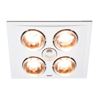
THERMALITE 3 IN 1 BATHROOM EXHAUST FAN
SKU# 200026, 200027, 200030, 200031, 200032, 200033
Rated Voltage 220-240V~ 50Hz
rating.
Advertisement

Subscribe to Our Youtube Channel
Related Manuals for LUCCI THERMALITE 3 IN 1


Summary of Contents for LUCCI THERMALITE 3 IN 1
-
Page 1: Installation Instructions
SKU# 200026, 200027, 200030, 200031, 200032, 200033 Rated Voltage 220-240V~ 50Hz Thank you for purchasing this quality Lucci product. To ensure correct function and safety, please read and follow all instructions carefully before using the product. Please keep instructions for future reference. - Page 2 Installation Instructions 8. Insert the unit into the square hole ensuring to pull the side springs inward so that the body can pass through the hole without damaging the plaster. Ensure that the unit is held securely in place by the clips. If required, additional screws can be used to aid holding the unit in the ceiling.
- Page 3 Installation Instructions Safety tips • Always ensure the power is OFF and the lamp has cooled down before performing any maintenance, cleaning, changing the globe or adjustment to the fan. • Do not touch the globe with bare hands. Use a clean cloth, gloves or a tissue. •...
- Page 4 BATHROOM HEATER WARRANTY CARD Every Lucci Thermalite 3 in 1 is thoroughly inspected and tested before being released for sale. In addition to any warranties or conditions implied by applicable Statue or Regulation, Lucci Design warrants all of it’s bathroom heaters against defective workmanship and faulty materials for thirty six (36) months from the original date of purchase.
Need help?
Do you have a question about the THERMALITE 3 IN 1 and is the answer not in the manual?
Questions and answers