
Related Manuals for ARRI L1.0009652


Summary of Contents for ARRI L1.0009652
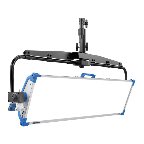
- Page 1 S120 S E R V I C E M A N U A L Date: September 26, 2016 Supported Models L1.0009652 / L1.0009653...
-
Page 2: Table Of Contents
Version History Version Author Change Note 09 / 2016 O. Hofmann Original version Table of Contents Version History ........................2 Table of Contents ....................... 2 Important Information......................3 Safety Instructions ......................3 ESD Safety Instructions ....................4 ESD Important Preparations ..................... 5 Relevant Hazard Symbols and Warnings ................ -
Page 3: Important Information
Please also refer to the Ordinance on Industrial Safety and Health as well as the relevant guidelines and regulations of your national Industrial Injuries Corporation (e.g. BGI 810-1, -3 and -4, BGV A1 for Germany; OSHA or ESTA for USA; etc.). Please refer also to our leaflet "Operating your ARRI Lamp heads safely" L5.70431.E. -
Page 4: Esd Safety Instructions
ESD Safety Instructions ESD sensitive components This symbol indicates the susceptibility to ESD sensitive components. If a repair instruction contains this symbol, you must take care of the ESD safety preparations mentioned below. ESD safety symbols This symbol indicates ESD protection devices. ESD workstation General Information Keep your workplace clean and make sure that you don’t use materials which generate static charge. -
Page 5: Esd Important Preparations
ESD Important Preparations 1. Plug the adapter into a standard power socket. 2. Connect the ground wire to the ESD table-mat. 3. Put the bracelet on. It’s important that it is placed on bare skin. Connect the contact of the band with the corresponding port on the ESD-protected mat. -
Page 6: Relevant Hazard Symbols And Warnings
Relevant Hazard Symbols and Warnings Please be aware of the following symbols and their meaning. Affected steps are marked in the Service Manual. Warning of crushing / hand injury Warning of a pointed object Warning of electrical voltage S120 – Service Manual Advanced Page 6 of 13... -
Page 7: Assembling Instructions
Assembling Instructions Follow the disassembling steps in reverse to reassemble the individual components. Any additional necessary steps are noted on the disassembling pages. Disassembling Order The graphic shows in which order the components must be removed to ensure a proper repair. All components which are not preceded by a further assembly group can be exchanged directly. -
Page 8: Required Tools
Required Tools Warning: Before starting the repair please take note of the safety instructions! Make sure that the lamp head is fully disconnected from the mains and cooled down before opening the cover or beginning the repair. 1 Allen Key 2.5mm 2 Torx TX 10 screw driver 3 Torx TX 15 screw driver 4 Torx TX 20 screw driver... -
Page 9: Connector Housing
Connector Housing Affected Components 1. Lay the lamphead facedown. 2. Loosen the shown screws with a Torx screw driver. 3. Take off the connector housing. S120 – Service Manual Advanced Page 9 of 13... -
Page 10: Handle / Control Panel
Handle / Control Panel Affected Components 1. Loosen the three shown screws with a Torx screw driver. 2. Take out the control panel as shown in the picture carefully (flat ribbon cable is connected). 3. Take out the control panel completely and disconnect the flat ribbon cable. -
Page 11: Housing
Housing Affected Components 1. Loosen the three shown screws with a Torx screw driver. 2. Loosen the screws on the both top latches with a Torx screw driver. 3. Loosen the three shown screws with a Torx screw driver. 4. Loosen the 8 shown screws with a Torx screw driver. - Page 12 5. Press the electronic unit to the front carefully. 6. Make sure to hold it as shown in the picture. 7. Take out the electronic unit carefully. 8. Use the assembly stand as shown in the picture. Lay the electronic unit facedown. S120 –...
-
Page 13: Contact
The manufacturer disclaims liability for any damage to persons or properties which are caused by an inappropriate operation of the fixture. Those lie in the responsibility of the operator. Visit our homepage www.arri.com/service-lighting for downloads and software tools. S120 – Service Manual Advanced...
Need help?
Do you have a question about the L1.0009652 and is the answer not in the manual?
Questions and answers