Napoleon B35NT Installation And Operation Manual
Hide thumbs
Also See for B35NT:
- Installation and operating instructions manual (116 pages) ,
- Installation and operating instructions manual (128 pages)
Table of Contents
Advertisement
NATURAL GAS MODELS:
PROPANE GAS MODELS:
SAFETY INFORMATION
WARNING
!
FIRE OR EXPLOSION HAZARD
Failure to follow safety warnings exactly
could result in serious injury, death, or
property damage.
- Do not store or use gasoline or other
fl ammable vapors and liquids in the vicinity of
this or any other appliance.
- WHAT TO DO IF YOU SMELL GAS:
•
Do not try to light any appliance.
•
Do not touch any electrical switch; do not
use any phone in your building.
•
Immediately call your gas supplier from a
neighbour's phone. Follow the gas
supplier's instructions.
•
If you cannot reach your gas supplier, call
the fi re department.
- Installation and service must be
performed by a qualifi ed installer, service
agency, or the supplier.
This appliance may be installed in an aftermarket,
permanently located, manufactured home (USA
only) or mobile home, where not prohibited by
local codes.
This appliance is only for use with the type of gas
indicated on the rating plate. This appliance is
not convertible for use with other gases, unless
a certifi ed kit is used.
INSTALLER:
Leave this manual with the appliance
CONSUMER:
Retain this manual for future reference
Wolf Steel Ltd., 24 Napoleon Rd., Barrie, ON, L4M 0G8 Canada / 103 Miller Drive, Crittenden, Kentucky, USA, 41030
Phone 1 (866) 820-8686 • www.napoleonfi replaces.com • hearth@napoleonproducts.com
$10.00
B35NT / B35NTE
ADD PRODUCT CODE HERE (TRADE GOTHIC LT STD FONT)
B35PT / B35PTE
INSTALLATION AND
ADD MANUAL TITLE
OPERATION MANUAL
CERTIFIED TO THE CANADIAN AND AMERICAN NATIONAL STANDARDS:
CSA 2.22 AND ANSI Z21.50 FOR VENTED DECORATIVE GAS APPLIANCES
IF INSTALLATION + OPERATION, ADD SERIAL
CSA /
INTERTEK
BARCODE LABEL ON THE OWNER'S MANUAL"
LOGO
Product Name / Code
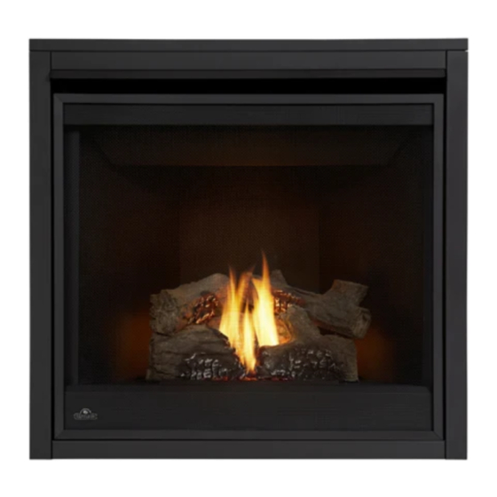
Ascent™ 35
(MUST use title from Price Book)
ADD ____ ILLUSTRATED
ADD PRODUCT IMAGE
FOR INDOOR USE ONLY
NUMBER LABEL HERE
IF SEPARATE MANUALS, ADD "PLACE
ENGLISH
FRENCH PG. 67
W415-1399 / C / 08.16.18
Advertisement
Table of Contents
Troubleshooting

Related Manuals for Napoleon B35NT


Summary of Contents for Napoleon B35NT
- Page 1 INTERTEK BARCODE LABEL ON THE OWNER’S MANUAL” LOGO Wolf Steel Ltd., 24 Napoleon Rd., Barrie, ON, L4M 0G8 Canada / 103 Miller Drive, Crittenden, Kentucky, USA, 41030 Phone 1 (866) 820-8686 • www.napoleonfi replaces.com • hearth@napoleonproducts.com $10.00 W415-1399 / C / 08.16.18...
- Page 2 safety information WARNING DANGER • This appliance is hot when operated and can cause severe burns if contacted. • Any changes or alterations to this appliance or its controls can be dangerous and is prohibited. HOT GLASS WILL CAUSE • Do not operate appliance before reading and BURNS.
- Page 3 patterns. safety information WARNING • Do not use a blower insert, heat exchanger insert or other accessory not approved for use with this appliance. • This appliance must not be connected to a chimney fl ue pipe serving a separate solid fuel burning appliance.
-
Page 4: Table Of Contents
table of contents general information finish framing rates and efficiencies minimum framing dimensions installation overview 10.0 finishing rating plate information 10.1 safety barrier / door removal and mobile home installation installation dimensions 10.2 front hood installation venting requirements 10.3 non-combustible facing material typical vent installation 10.4 minimum mantel clearances... -
Page 5: Rates And Efficiencies
Date of Installation: Location of appliance: Installer: Dealer/Distributor contact number: Serial #: Model: Natural Gas: B35NT Propane: B35PT B35NTE B35PTE 1.0 general information When the appliance is installed at elevations above 4,500 ft (1371m), and in the absence of specific recommendations from the local authority having jurisdiction, the certified high altitude input rating shall be reduced at the rate of 4% for each additional 1,000 ft (305m). -
Page 6: General Information
general information installation overview Recommended installation steps: 1. Determine venting requirements before deciding the final location of the appliance. 2. Install rough framing (see “rough framing” section). 3. Place the appliance in its final position. 4. Install appliance venting (see “venting installation” section). 5. - Page 7 general information WARNING • Always light the pilot - whether for the first time or if the gas supply has run out - with the glass door opened or removed. • Provide adequate clearance for servicing and operating the appliance. •...
-
Page 8: Rating Plate Information
OPTIONAL FAN KIT / ENSEMBLE DE VENTILATEUR FACULTATIF: EP35 WOLF STEEL LTD. SERIAL NUMBER/NO. DE SERIE: 24 NAPOLEON ROAD, BARRIE, ON, L4M 0G8 CANADA W385-1925 / F This illustration is for reference only. Refer to the rating plate on the appliance for accurate information. -
Page 9: Dimensions
general information dimensions W415-1399 / C / 08.16.18... -
Page 10: Venting Requirements
2.0 venting requirements WARNING • Risk of fi re. Maintain specifi ed air space clearances to vent pipe and appliance. • The vent system must be supported every 3’(0.9m) for both vertical and horizontal runs. Use support ring assembly W010-0067 or equivalent non-combustible strapping to maintain the minimum clearance to combustibles for both vertical and horizontal runs. - Page 11 venting requirements FOR 4” / 7” (USE REDUCER KIT 4758AK TO TRANSITION FROM 5” / 8” TO 4” /7” VENTING) When using Wolf Steel venting components, use only approved Wolf Steel rigid / flexible components with the following termination kits: wall terminal kit GD222, GD222R, or 1/12 to 7/12 pitch roof terminal kit GD110, 8/12 to 12/12 roof terminal kit GD111, flat roof terminal kit GD112 or periscope kit GD201 (for wall penetration below grade).
-
Page 12: Typical Vent Installation
venting requirements typical vent installation 16" (40.6cm) minimum 40 ft (12m) maximum 24" (61cm) 3 ft (1m) maximum minimum 8" (20.3cm) minimum 34 5/8" (87.9cm) TOP VENT W415-1399 / C / 08.16.18... -
Page 13: Special Vent Installations
venting requirements special vent installations 2.2.1 periscope termination Use the periscope kit to locate the air termination above grade. The periscope must be installed so that when fi nal grading is completed, the bottom air slot is located a minimum 12” (305mm) above grade. The maximum allowable vent length (including both rise and run) is 10’... -
Page 14: Minimum Air Terminal Location Clearances
venting requirements minimum air terminal location clearances Covered balcony applications ††* = 3 feet ≤ 15 feet = 2 x ACTUAL (0.9m) (4.6m) note: INSTALLATIONS Wall terminals are for illustration purposes only. Size and shapes may vary. CANADA U.S.A. 12” (30.5cm) 12”... -
Page 15: Venting Application Flow Chart
venting requirements venting application flow chart TOP EXIT Horizontal Termination Vertical Termination Vertical rise is equal Vertical rise is equal Vertical rise is less Vertical rise is less to or greater than to or greater than than horizontal run than horizontal run the horizontal run the horizontal run Horizontal run +... -
Page 16: Converting From 5/8" To 4/7" Venting
venting requirements converting from 5/8" to 4/7" venting note: You may reduce the appliance from 5/8" to 4/7" venting for horizontal runs with a vertical rise application. 2.7.1 reduced vent clearance to combustibles The minimum clearances around the horizontal vent pipe to the combustible material may be reduced from 3"... -
Page 17: Adaptor Kit (4758Ak)
venting requirements 2.7.2 adaptor kit (4758AK) note: The adaptor must be installed directly onto the appliance collars before vertical rise. TAKE VENT MEASUREMENTS FROM THE TOP OF THE ADAPTOR ADAPTOR KIT When using the adaptor kit (4758AK), vent measurements must be taken from the top of the adaptor to the 4/7"... -
Page 18: Top Exit Horizontal Termination
venting requirements top exit horizontal termination ) ≤ (V See graph to determine the required vertical rise V Simple venting configuration (only one 90° elbow) the required horizontal run H 40 (12.2) 40 (12.2) 39 (11.9) 39 (11.9) Required vertical REQUIRED 30 (9.1) 30 (9.1) - Page 19 venting requirements ) > (V See graph to determine the required vertical rise V Simple venting configuration (only one 90° elbow) the required horizontal run H 12.3 (3.8) REQUIRED VERTICAL RISE IN 8.3 (2.5) FEET (METERS) V 4.8 (1.5) 4.2 (1.3) 1.6 (5) 20 (6.1) (1.5)
-
Page 20: Top Exit Vertical Termination
venting requirements top exit vertical termination ) < (V Simple venting configurations. See graph to determine the required vertical rise V for the required horizontal run H 40 (12.2) 30 (9.1) Required vertical rise in feet 20 (6.1) (meters) V 10 (3.1) 3 (0.9) (1.5) - Page 21 venting requirements ) > (V Simple venting configurations. See graph to determine the required vertical rise V for the required horizontal run H 20 (6.1) 19 (5.8) Required vertical rise in feet 10 (3.1) (meters) V 3 (0.9) 10 (3.1) (7.6) (9.1) (1.5)
-
Page 22: Rough Framing
3.0 rough framing note: When using optional fi nishing accessories, the framing dimensions and fi nishing materials may differ from what is outlined in the section below; refer to the leafl et instructions supplied in the accessory kit for specifi c framing and fi nishing specifi cations. -
Page 23: Minimum Framing Dimensions
rough framing minimum framing dimensions HORIZONTAL VENT SECTIONS: A minimum of 1" (25mm) at the bottom and sides and 3" (76mm) at the top of the vent pipe on all horizontal runs to combustibles is required. Use firestop spacer W010-1800 (supplied). note: The minimum clearances from the top of the horizontal vent pipe to combustible materials may be reduced from 3"(76mm) to 1"(25mm) in those installations with a minimum 38"... -
Page 24: Minimum Enclosure Clearances
rough framing minimum enclosure clearances TOP VENT 34 5/8" (87.9cm) TOP EXIT ENCLOSURE The appliance requires a minimum enclosure height of 50 1/2" (128.3cm). For temperature requirements, the enclosure space around and above the appliance must be left unobstructed. note: The vent shield is telescopic and must be adjusted to shield the full depth of the combustible wall penetration. - Page 25 rough framing note: For heavier finishing materials such as marble, we recommend adding extra support to the frame. Ensure there is adequate floor support for the appliance and finishing material. Before framing your appliance, determine vent requirements before deciding the final location of the appliance. After rough framing, place the appliance in its final position.
-
Page 26: Venting Installation
4.0 venting installation WARNING • Ensure to unpack all loose materials from inside the fi rebox prior to connecting the gas and electrical supply • If your appliance is supplied with a remote, ensure the remote receiver is in the “OFF” position prior to connecting the gas and electrical supply to the appliance. -
Page 27: Horizontal Installation
venting installation horizontal installation WARNING • The fi restop assembly must be installed with the vent shield to the top. • Terminals must not be recessed into a wall or siding more than the depth of the return fl ange of the mounting plate. -
Page 28: Using Either Flexible Vent Components
venting installation using either flexible vent components WARNING • Do not allow the inner fl ex pipe to bunch up on horizontal or vertical runs and elbows. Keep it pulled tight. • Spacers are attached to the inner fl ex pipe at predetermined intervals to maintain an even air gap to the outer fl ex pipe. -
Page 29: Vertical Air Terminal Installation
venting installation 4.3.2 vertical air terminal installation WARNING • Maintain a minimum 2” (51mm) space between the air inlet base and the storm collar. note: Fastening hardware provided with appropriate roof terminal and liner kits. Fasten the roof support to the roof using 6 screws. The roof support is optional. -
Page 30: Horizontal Air Terminal Installation
venting installation 4.3.4 horizontal air terminal installation Move the appliance into position. Measure #10x2" the vent length required between terminal and SCREWS appliance taking into account the additional CAULKING length needed for the fi nished wall surface and any 2” (50.8mm) overlaps between venting INNER components. -
Page 31: Vertical Air Terminal Installation
venting installation 4.3.5 vertical air terminal installation WARNING • Maintain a minimum 2” (51mm) space between the air inlet base and the storm collar. note: Fastening hardware provided with appropriate roof terminal and liner kits. Before attaching elbows to the collars on the back of the appliance, 1 1/2” (38.1mm) will need to be trimmed off the 4”... -
Page 32: Vertical Through Existing Chimney
venting installation vertical through existing chimney WARNING • Risk of fi re. • Co-axial to co-linear venting confi gurations must only be used in a non-combustible chimney or enclosure. Installation in a combustible enclosure could result in a fi re. This appliance is designed to be attached to a 3”... -
Page 33: Restricting Vertical Vents
venting installation 4.4.1 restricting vertical vents WARNING • Turn off gas and electrical supply before servicing the appliance. • Appliance may be hot. Do not service until appliance is cool. • For safe and proper operation of the appliance, follow the venting instructions exactly. •... -
Page 34: Electrical Information
5.0 electrical information wiring diagram WARNING • Do not wire 110 volts to the valve or wall switch. ACS/IPI SWITCH (OPTIONAL) GREEN ON / OFF ORANGE SWITCH TRANSFORMER IPI / CPI ON / OFF BATTERY HOUSING ELECTRONIC DISCONNECT THESE VALVE CONNECTIONS TO THE ON/OFF SWITCH. -
Page 35: Battery Backup Installation
electrical information battery backup installation WARNING • Ensure the gas and electrical power to the appliance is turned off. • Appliance may be hot. Do not service until the appliance has cooled. note: In the event of a power failure, your appliance can be operated using the battery back-up supplied. Before beginning installation, disconnect the gas and electrical power supply from the appliance. -
Page 36: Optional Wall Switch
electrical information optional wall switch WARNING • Do not connect either the wall switch, thermostat or gas valve directly to 110 volt electricity. For ease of accessibility, an optional remote wall switch or millivolt thermostat may be installed in a convenient SIT MILLIVOLT location. -
Page 37: Gas Installation
6.0 gas installation WARNING • Risk of fi re, explosion, or asphyxiation. Ensure there are no ignition sources such as sparks or open fl ames. • Support gas control when attaching gas supply pipe to prevent damaging gas line. • Always light the pilot whether for the fi rst time or if the gas supply has run out with the glass door opened or removed. -
Page 38: Operation (Electronic)
7.0 operation (electronic) WARNING • If you do not follow these instructions exactly, a fi re or explosion may result causing property damage, personal injury, or loss of life. • If applicable, always light the pilot whether for the fi rst time or if the gas supply has run out with the glass door opened or removed. -
Page 39: Operation (Millivolt)
8.0 operation (millivolt) WARNING • If you do not follow these instructions exactly, a fi re or explosion may result causing property damage, personal injury, or loss of life. • If applicable, always light the pilot whether for the fi rst time or if the gas supply has run out with the glass door opened or removed. -
Page 40: Finish Framing
9.0 finish framing 18 9/16" minimum framing dimensions 471mm 35" 889mm 18 9/16" 471mm W415-1399 / C / 08.16.18... -
Page 41: Finishing
10.0 finishing WARNING • Risk of fire! • Never obstruct the front opening of the appliance. • The front of the appliance must be finished with any non-combustible materials such as brick, marble, granite, etc., provided that these materials do not go below the specified dimension, as illustrated. •... -
Page 42: Front Hood Installation
finishing 10.2 front hood installation note: This hood MUST be installed, if it has not already been factory installed. Safety door and screen must be removed. Remove the securing screws from the top of the firebox, as shown. Install the front hood, ensure it is angled downward when installed. Reinstall the previously removed securing screws. -
Page 43: Non-Combustible Facing Material
finishing 10.3 non-combustible facing material WARNING Non-combustible facing material must not project more than 4” (101.6mm) from the face of the door (all four sides). If greater projections are desired, increase the clearance to the sides, bottom and top by 2” (50.8mm) for every additional 1”... -
Page 44: Minimum Mantel Clearances
finishing 10.4 minimum mantel clearances WARNING TOP OF APPLIANCE • Risk of fi re. Maintain all specifi ed air space clearances to combustibles. Failure to comply with these instructions may cause a fi re or cause the appliance to overheat. Ensure all clearances (i.e. back, side, top, vent, mantel, front, etc.) are clearly maintained. -
Page 45: Recessed Installation
finishing 10.5 recessed installation WARNING • Installing a television or other electronics above the appliance may cause discolouration, melting, or damage to the electronics. Use clearances as guidelines and refer to your manufacturer's instructions for further information. MINIMUM CLEARANCES CHART 6"... -
Page 46: Nailing Tab Installation
finishing 10.6 nailing tab installation Nailing tabs are provided as part of the frames, as shown. To determine the final location and where to bend the nailing tabs you must first determine the thickness of your finishing material (i.e. IMAGE drywall). -
Page 47: Log Placement
finishing 10.7 log placement WARNING • Failure to position the logs in accordance with these diagrams or failure to use only logs specifi cally approved with this appliance may result in property damage or personal injury. • Logs must be placed in their exact location in the appliance. Do not modify the proper log positions, since appliance may not function properly and delayed ignition may occur. -
Page 48: Glowing Embers
finishing Reinstall the door and safety screen (see "safety barrier / door removal and installation" section). Place the right crossover log (W135-0589) onto the pin located in the right side of the rear log, allow it to rest in the notch of the right log. 10.8 glowing embers WARNING... -
Page 49: Optional (Aub) Blower Installation
NOTE: fOr mOrE dETailEd iNsTrucTiONs rEfEr TO yOur iNsTallaTiON maNual. NOTE: fOr mOrE dETailEd iNsTrucTiONs rEfEr TO yOur iNsTallaTiON maNual. W415-1479 / A / 05.09.16 W415-1479 / A / 05.09.16 Wolf Steel Ltd., 24 Napoleon Rd., Barrie, ON L4M 0G8 Canada • (705)721-1212 • fax (705)720-9081 • www.napoleonfireplaces.com Wolf Steel Ltd., 24 Napoleon Rd., Barrie, ON L4M 0G8 Canada... -
Page 50: Adjustment
12.0 adjustment 12.1 pilot burner adjustment Adjust the pilot screw to provide properly sized fl ame. Turn in a clockwise direction to reduce the gas fl ow. Check Pressure Readings: PILOT 3/8” - 1/2” Inlet pressure can be checked by turning screw (A) counter- ELECTRODE BURNER ELECTRONIC... -
Page 51: Venturi Adjustment
Flame must envelope La flam upper la ther adjustment 3/8" to 1/2" (12.7mm - 9.5mm) of 12.2 venturi adjustment thermocouple This appliance has an air shutter that has been factory set open according to the chart below: VENTURI Regardless of venturi orientation, closing the air shutter will cause a more BURNER yellow flame, but can lead to carbonization. -
Page 52: Maintenance
13.0 maintenance WARNING • Turn off the gas and electrical power before servicing the appliance. • Appliance may be hot. Do not service until appliance has cooled. • Do not use abrasive cleaners on glass. • Do not paint the pilot assembly. This appliance and its venting system should be inspected before use and at least annually by a qualifi ed service person. -
Page 53: Door Glass Replacement
• Using a vacuum with soft brush attachment, gently remove any dirt, debris, or carbon build up from the logs, fi rebox, and burner. For glass media, follow the installation instructions for pre-cleaning. • Gently remove any build-up on the pilot assembly including thermopile, thermocouple, fl ame sensor, and maintenance igniter (if equipped). -
Page 54: Replacement Parts
14.0 replacement parts WARNING • Failure to position the parts in accordance with this manual or failure to use only parts specifi cally approved with this appliance may result in property damage or personal injury. Contact your dealer for questions concerning prices and policies on replacement parts. Normally, all parts can be ordered through your Authorized dealer / distributor. -
Page 55: Overview
replacement parts W415-1399 / C / 08.16.18... -
Page 56: Electronic Valve Train Assembly
replacement parts W415-1399 / C / 08.16.18... -
Page 57: Millivolt Valve Train Assembly
replacement parts W415-1399 / C / 08.16.18... -
Page 58: Accessories
15.0 accessories W415-1399 / C / 08.16.18... -
Page 59: Troubleshooting (Electronic)
16.0 troubleshooting (electronic) WARNING • Always light the pilot whether for the fi rst time or if the gas supply has run out, with the glass door open or removed. • Turn off gas and electrical power before servicing the appliance. •... - Page 60 troubleshooting (electronic) symptom problem test solution Pilot will not light. Makes Wiring: short, loose, or damaged Verify the thermocouple/sensor is clean and the wiring is undamaged. noise with no spark at connections Verify the interrupter block is not damaged or too tight. Verify connections from pilot assembly are tight;...
- Page 61 Wire connector pins are bent. Straighten pins. Valve wiring is damaged. Replace valve. troubleshooting (electronic) symptom problem test solution Motor is turning, Receiver batteries low. Replace batteries. frequent beeping occurs. Lights or blower Control module switch in Verify ON/OFF switch is in the “I” position which denotes on. won’t function (if wrong position.
-
Page 62: Troubleshooting (Millivolt)
17.0 troubleshooting (millivolt) WARNING • Always light the pilot whether for the fi rst time or if the gas supply has run out, with the glass door open or removed. • Turn off gas and electrical power before servicing the appliance. •... - Page 63 troubleshooting (millivolt) symptom problem test solution Pilot will not light. No spark at pilot burner. Check if pilot can be lit by a match. Check that the wire is connected to the push button ignitor. Check if the push button ignitor needs tightening. PILOT Replace the wire if the wire insulation is broken or frayed.
-
Page 64: Warranty
President’s Limited Lifetime Warranty Policy are subject to a single claim. During the fi rst 10 years Napoleon will replace or repair the defective parts covered by the lifetime warranty at our discretion free of charge. From 10 years to life, Napoleon will provide replacement parts at 50% of the current retail price. All parts replaced under the warranty will be covered for a period of 90 days from the date of their installation. -
Page 65: Service History
19.0 service history W415-1399 / C / 08.16.18... - Page 66 NAPOLEON CELEBRATING OVER 40 YEARS OF HOME COMFORT PRODUCTS 7200, Route Transcanadienne, Montréal, Québec H4T 1A3 24 Napoleon Road, Barrie, Ontario, Canada L4M 0G8 214 Bayview Drive, Barrie, Ontario, Canada L4N 4Y8 103 Miller Drive, Crittenden, Kentucky, USA 41030 Phone: 1-866-820-8686...
Need help?
Do you have a question about the B35NT and is the answer not in the manual?
Questions and answers