Table of Contents
Advertisement
Advertisement
Table of Contents

Related Manuals for Blade Fusion 480


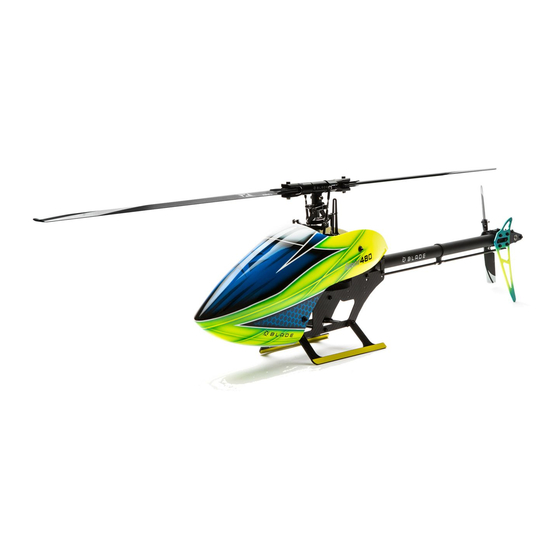
Summary of Contents for Blade Fusion 480
- Page 1 Instruction Manual Bedienungsanleitung Manuel d’utilisation Manuale di Istruzioni...
- Page 2 NOTICE All instructions, warranties and other collateral documents are subject to change at the sole discretion of Horizon Hobby, LLC. For up-to-date product literature, visit horizonhobby.com and click on the support tab for this product. Meaning of Special Language The following terms are used throughout the product literature to indicate various levels of potential harm when operating this product: WARNING: Procedures, which if not properly followed, create the probability of property damage, collateral damage, and serious injury OR create a high probability of superfi...
-
Page 3: Table Of Contents
Canopy Installation ..................18 Tools Needed To Complete ................3 Flight Guidelines and Warnings ................ 19 ! BEFORE STARTING ASSEMBLY! ............... 4 Flying Your Fusion 480 ..................19 Head Assembly ....................4 Blade Tracking ....................19 Frame Assembly ....................5 Post-Flight Inspection and Maintenance ............ -
Page 4: Before Starting Assembly
! BEFORE STARTING ASSEMBLY! Many of the major sub-assemblies of the Blade Fusion 480 kit have been pre-assembled at the factory. These sub-assemblies were not assembled with thread-locking compound. Prior to beginning assembly of the kit, loosen any pre-assembled screws which are threaded into metal components and apply thread-locking compound. Use only enough thread-locking compound to moisten the threads. -
Page 5: Frame Assembly
Step H3 1. Snap the follower arms onto two opposite linkage balls on the upper swashplate. 2. Adjust the length of the rotor head linkages to 55mm 55mm from center to center of the link openings. 3. Snap the rotor head linkages onto the main grip linkage balls. - Page 6 Step F2 1. Attach the upper and lower bearing blocks to the frame sides using 3x10mm screws, machined washers and medium thread-locking compound. The upper block has two threaded holes in the rear of the block. Do not fully tighten the screws in the bearing blocks at this time.
- Page 7 Step F4 1. Remove the 3x18mm socket head cap screws of the tail belt guide assembly and re-install them using medium thread-locking compound. Ensure the thread-locking compound does not contact the bearings of the tail guide assembly. 2. Install the tail belt guide between the frame sides using 3x10mm screws and medium thread-locking compound.
- Page 8 Step F5 1. Pull the tail belt pulley off of the one-way bearing sleave. Remove ten 2x4mm fl athead screws from the tail drive pulley one at a time and re-install them using medium thread-locking compound. 2. Remove fi ve 3x6mm fl athead screws one at a time from the main gear and re-install them using medium thread-locking compound.
- Page 9 Step F7 1. If using the recommended speed control, attach the Hook and speed control mount, included with the speed control, loop strap to the bottom side of the battery plate. Secure a hook and loop strap between the battery plate and the speed control mount, as shown.
- Page 10 Step F8 20mm Prepare three cyclic servos as follows: Rotor head removed for clarity 1. Center the servos using either your receiver or a servo tester. 2. Attach the servo arm in the position shown, perpendicular to the servo case, using the screw provided with the servo and medium thread-locking compound.
-
Page 11: Tail Assembly
Tail Assembly (T) Step T1 1. Slide two front tailboom mounts over the front of the tail boom. The Blade ® logo is towards the front of the tailboom. 2. Attach the mounts to the tailboom using one M3x6mm button head screw per mount and medium thread-locking compound, into the holes in the top of the tailboom. - Page 12 Tail Assembly (T) Step T2 1. Slide the tail pushrod guide onto the tailboom. The guide should be located approximately in the center of the tailboom. 2. Slide two rear tailboom mounts over the tailboom. 3. Attach the mounts using two 3x6mm button head screws per mount and medium thread-locking compound, into the holes on either side of the tailboom.
- Page 13 Tail Assembly (T) Step T4 1. Remove the tail grip retention screws and linkage balls and re-install them using medium thread- locking compound. Ensure the thread-locking compound does not contact the tail grip bearings. 2. Insert the tail shaft into the tail rotor hub assembly. 3.
- Page 14 Tail Assembly (T) Step T6 1. Check the belt tension just behind the main gear at the rear of the side plate opening. Push inward on the belt from the side with moderate pressure. The belt should not defl ect more 4mm. 2.
-
Page 15: Flight Controller Mounting
Hook and loop straps Helicopter Setup The following are optimal settings for the Blade Fusion 480, obtained through extensive fl ight testing. Refer to your fl ybarless fl ight controller and transmitter manuals for proper setup. Collective Pitch Range Head Speed... -
Page 16: Main Rotor Alignment
With the servos centered and arms level, the swashplate should be level and the 0 degree collective indication marks on top of the blade grips and headblock should align, as shown. Adjust the lengths of the blade grip linkages and servo linkages until everything is aligned properly. - Page 17 Thoroughly review your chosen fl ight control system manual to ensure the system is confi gured properly, per the manufacturer’s recommendations. WARNING: Disconnect the motor from the electronic speed control or ensure the transmitter throttle hold function is properly confi gured and ON prior to performing the cyclic and collective control tests.
-
Page 18: Tail Rotor Blade Installation
Main Rotor Blade Installation Install the main rotor blades in the orientation shown using 4x30mm bolts, plastic blade shims and locknuts. Do not apply thread lock compound to the bolt and lock nut. -
Page 19: Flight Guidelines And Warnings
(45 feet) when checking the main rotor blade tracking. 1. Put the helicopter in a hover at an altitude near eye height. 2. Watch the movement at the blade tips. Both blades should travel in the same plane. WARNING: Always wear protective safety glasses when checking the main rotor blade tracking. -
Page 20: Troubleshooting Guide
Troubleshooting Guide Problem Possible Cause Solution Flight battery has low voltage Fully charge the fl ight battery Helicopter power is lacking Flight battery is old or damaged Replace the fl ight battery Flight battery cells are unbalanced Fully charge the fl ight battery, allowing the charger time to balance the cells Transmitter settings are not correct Check throttle and pitch curve settings and pitch control direction Helicopter will not lift off... -
Page 21: Warranty And Service Contact Information
Non-Warranty Service ATTENTION: Horizon service is limited to Product compliant in the Should your service not be covered by warranty, service will be completed and country of use and ownership. If received, a non-compliant Product will payment will be required without notifi cation or estimate of the expense unless the not be serviced. -
Page 22: Exploded View
Exploded View / Explosionszeichnung / Vue éclatée / Vista esplosa... - Page 23 Exploded View / Explosionszeichnung / Vue éclatée / Vista esplosa...
-
Page 24: Parts List
Parts List / Ersatzteile / Pièces de rechange / Pezzi di ricambio Part # English Deutsch Français Italiano BLH4901 480mm CF Main Rotor Blades (2) 480 mm CF Hauptrotorblätter (2) Pales du rotor principal 480 mm CF (2) Pale rotore principale 480 mm CF (2) BLH4902 Main Rotor Grip Hauptrotorhalter Poignée du rotor principal... -
Page 25: Recommended Components
Bürstenloser Motor: 4020-1350 kV Moteur sans balais : 4020-1 350 Kv Motore brushless: 4020-1350Kv Arbre de 5 mm du Pignon 11t : BLH4962 11t Pinion 5mm Shaft: Fusion 480 11T Ritzel 5 mm Welle: Fusion 480 Pignone 11t Albero 5 mm: Fusion 480 Fusion 480 SPMSH6050 H6050 H-T M-S Heli Cyclic Servo H6050 H-T M-S Hubschrauber-Steuerservo Servo cyclique H6050 H-T M-S Heli Servo ciclico H6050 H-T M-S elicottero Servo d’empennage H6060 M-T... - Page 26 ©2018 Horizon Hobby, LLC. Blade, the Blade logo, EC5, DSM, DSM2, DSMX and the Horizon Hobby logo are trademarks or registered trademarks of Horizon Hobby, LLC. The Spektrum trademark is used with permission of Bachmann Industries, Inc. Created 5/18 50111...
Need help?
Do you have a question about the Fusion 480 and is the answer not in the manual?
Questions and answers