Advertisement
Quick Links
Download this manual
See also:
User Manual
Advertisement

Summary of Contents for Lexmark C2240
-
Page 1: Service Manual
C2240, C2325, C2425, C2535, CS421, CS521, CS622 5029-038,23x, 43x, 6x6 Service Manual • Start diagnostics • Maintenance • Safety and notices • Trademarks • Index June 29, 2018 www.lexmark.com... -
Page 2: Product Information
Trademarks Lexmark and the Lexmark logo are trademarks of Lexmark International, Inc., registered in the United States and/or other countries. PCL® is a registered trademark of the Hewlett-Packard Company. PCL is Hewlett-Packard Company’s designation of a set of printer commands (language) and functions included in its printer products. -
Page 3: General Information
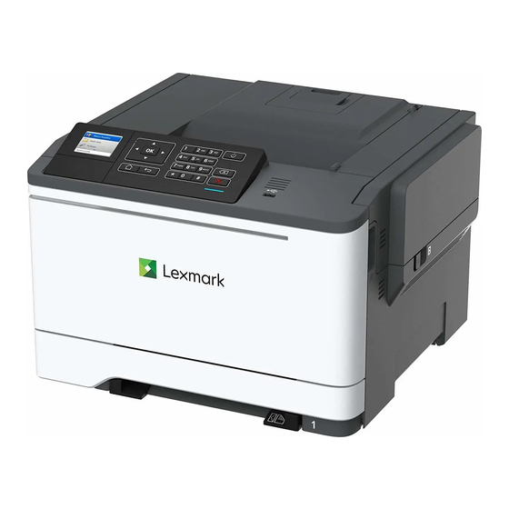
Printer model configurations The Lexmark C2240, C2325, C2425, C2535, CS421, CS521, CS622 printers are network‑capable, multifunction laser printers. The printers support color and monochrome printing and are embedded with home screen solutions and applications. All information in this service manual pertains to all models unless explicitly noted. -
Page 4: Parts Catalog
5029 Parts catalog Legend The following column headings are used in the parts catalog: • Asm‑index—Identifies the item in the illustration • P/N—Identifies the part number of a FRU • Units/mach—Refers to the number of units in a printer • Units/opt—Refers to the number of units in an option •... - Page 5 5029 Assembly 1: 2-line control panel Parts catalog...
- Page 6 5029 Assembly 1: 2-line control panel Asm-index Units/mach Units/FRU Description Removal procedure 41X2070 CS321 control panel “2‑line control panel badge cover badge cover removal” on page 285 41X2127 SC2325 control panel “2‑line control panel badge cover badge cover removal” on page 285 41X2044 2-line control panel bezel “2‑line control panel bezel removal”...
- Page 7 5029 Assembly 2: 2.4-inch and 4.3-inch control panel Parts catalog...
- Page 8 5029 Assembly 2: 2.4-inch and 4.3-inch control panel Asm-index Units/mach Units/FRU Description Removal procedure 41X2049 CS421 control panel badge “2.4‑inch control panel badge cover cover removal” on page 286 41X2050 CS521 control panel badge “2.4‑inch control panel badge cover cover removal” on page 286 41X2132 SC2425 control panel “2.4‑inch control panel badge...
- Page 9 5029 Asm-index Units/mach Units/FRU Description Removal procedure 41X2134 C2240 control panel badge “4.3‑inch control panel badge cover cover removal” on page 286 41X2119 Control panel power cable -- Parts catalog...
- Page 10 5029 Parts catalog...
- Page 11 5029 Parts catalog...
- Page 12 5029 Assembly 3: Covers Parts catalog...
- Page 13 5029 Assembly 3: Covers Asm-index Units/mach Units/FRU Description Removal procedure 40X7633 Top cover “Top cover removal” on page 340 40X7621 Toner cover 40X9244 Front toner door bracket -- 41X0397 System fan “System fan removal” on page 336 41X2100 Rear cover, CS62x “Rear cover removal”...
- Page 14 5029 Parts catalog...
- Page 15 5029 Assembly 4: Paper path and frame Parts catalog...
- Page 16 5029 Assembly 4: Paper path and frame Asm-index Units/mach Units/FRU Description Removal procedure 41X2305 Fuser deflector “Exit deflector removal” on page 308 41X2349 Narrow media/bin full “Narrow media/bin full sensor flag flag removal” on page 346 41X2350 Right deflector flag “Right output bin deflector removal”...
- Page 17 5029 Assembly 5: Electronics Parts catalog...
- Page 18 5029 Assembly 5: Electronics Asm-index Units/mach Units/FRU Description Removal procedure 41X1789 Controller board (CS421 “Controller board removal” on and C2425) page 339 41X2098 Controller board (CS521 “Controller board removal” on and CS2535) page 339 41X1790 Controller board (CS622 “Controller board removal” on and CS2240) page 339 41X2140...
- Page 19 5029 Assembly 6: Cables and sensors Parts catalog...
- Page 20 5029 Assembly 6: Cables and sensors Asm-index Units/mach Units/FRU Description Removal procedure 41X1904 Sensor (left toner patch with “Sensors (toner patch) thermistor) removal” on page 261 41X2348 Sensor (right toner patch with “Sensors (toner patch) thermistor) removal” on page 261 41X1722 Waste toner bottle contact “Waste toner bottle contact...
- Page 21 5029 Assembly 7: Option trays Parts catalog...
- Page 22 5029 Assembly 7: Option trays Asm-index Units/mach Units/FRU Description Removal procedure 41X1783 Optional 650-sheet duo tray “650‑sheet duo tray removal” on page 350 40X5168 Pick tires “Pick tire removal” on page 352 41X1784 650-sheet duo tray insert “650‑sheet duo tray insert removal”...
- Page 23 5029 Assembly 8: Miscellaneous Asm-index Units/mach Units/FRU Description Removal procedure 41X2096 115 V Maintenance kit (fuser and transfer module) 41X2097 230 V Maintenance kit (fuser and transfer module) 41X2095 100 V Maintenance kit (fuser and transfer module) 40X9934 320 GB SATA hard disk drive 41X1373 SATA hard disk drive with FIPS 41X1873...


Need help?
Do you have a question about the C2240 and is the answer not in the manual?
Questions and answers