Table of Contents
Advertisement
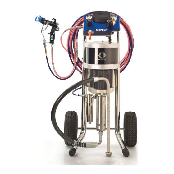
Instructions-Parts
Merkur
High Pressure Sprayer
For protective coating applications in hazardous or non-hazardous locations. For
professional use only.
See page 2 for model information, including maximum
working pressures.
Important Safety Instructions
Read all warnings and instructions in this
manual. Save these instructions.
®
Repair Kits
Accessory Kits
See page 25
ll 2 G Ex h T3 Gb
332245G
EN
ti21103a
Advertisement
Table of Contents

Related Manuals for Graco Merkur series


Summary of Contents for Graco Merkur series
- Page 1 Instructions-Parts Repair Kits Accessory Kits See page 25 ® Merkur High Pressure Sprayer 332245G For protective coating applications in hazardous or non-hazardous locations. For professional use only. See page 2 for model information, including maximum working pressures. Important Safety Instructions Read all warnings and instructions in this manual.
-
Page 2: Table Of Contents
Merkur X48 Package ..... 3 Graco Standard Warranty ....30 Merkur X72 Package . -
Page 3: Models
Models Models Merkur X48 Package Hoses Accessories Maximum Maximum Maximum Fluid Drain Inlet Air Fluid Working Fluid Flow Fluid Whip Suction Fluid Valve Pressure Pressure Rate Part Hose Hose Tube Filter psi (MPa, bar) psi (MPa, bar) gpm (lpm) Tip Size ✔... -
Page 4: Warnings
Warnings Warnings The following warnings are for the setup, use, grounding, maintenance, and repair of this equipment. The exclama- tion point symbol alerts you to a general warning and the hazard symbols refer to procedure-specific risks. When these symbols appear in the body of this manual or on warning labels, refer back to these Warnings. Product-specific hazard symbols and warnings not covered in this section may appear throughout the body of this manual where applicable. - Page 5 Warnings WARNING EQUIPMENT MISUSE HAZARD Misuse can cause death or serious injury. • Do not operate the unit when fatigued or under the influence of drugs or alcohol. • Do not exceed the maximum working pressure or temperature rating of the lowest rated system component.
-
Page 6: Installation
Installation Installation ti21104a . 1: Typical Installation Key: Air Shutoff Valve (optional accessory) Whip Hose Air Filter (optional accessory) Pump Fluid Outlet Bleed Type Master Air Valve Grounding Wire Pump Air Pressure Gauge Wet-Cup Pump Air Pressure Regulator Pump Fluid Inlet Cart Suction Hose Fluid Drain Valve... -
Page 7: General Information
NOTE: Always use Genuine Graco Parts and Accesso- required in your system to relieve air trapped ries, available from your Graco distributor. If you supply between it and the air motor when the valve is your own accessories, be sure they are adequately closed. -
Page 8: Grounding
. 2. Ground screw and wire 2. Pump fluid hoses: use only electrically conductive fluid hoses. Check electrical resistance of hoses. If total resistance to ground exceeds 25 megohms, replace hose immediately. Genuine Graco hoses are conductive. 3. Air compressor: follow manufacturer's recommen- dations. - Page 9 8. Flush before using. See page 11. 9. Prime before using. See page 12. Wet Cup Before starting, fill wet cup (N) 1/2 full with Graco Throat Seal Liquid (TSL) Part No. 206994, or compatible sol- vent. . 4. Wet Cup...
-
Page 10: Operation
Operation Operation Pressure Relief Procedure Trigger Lock Follow the Pressure Relief Procedure whenever you see this symbol. See F . 5. Always engage gun trigger lock when you stop spraying to prevent gun from being triggered acci- dentally by hand or if dropped or bumped. This equipment stays pressurized until pressure is manually relieved. -
Page 11: Flush
Operation Flush 4. Turn regulator adjustment knob (E) counterclock- wise until it stops, and gauge (D) reads zero. To avoid fire and explosion, always ground equipment and waste container. To avoid static sparking and injury from splashing, always flush at the lowest possible pressure. -
Page 12: Prime
Operation 7. If flushing through drain/purge valve: Prime a. Place drain tube in a grounded waste pail. Open drain/purge valve (S) slightly by rotating counterclockwise. 1. Follow Pressure Relief Procedure, page 10. 2. See F . 1. Lock gun trigger. Remove tip guard and spray tip from gun (H). -
Page 13: Install The Spray Tip
Operation 6. Prime through drain valve, if necessary (usually for 7. Prime hose and gun: one component, high viscosity materials): a. Disengage gun trigger lock. a. Place drain tube in a grounded waste pail. Open drain/purge valve (S) slightly by rotating counterclockwise. -
Page 14: Spray
Operation Spray 6. Disengage gun trigger lock. TI5048a NOTICE Do not allow pump to run dry. It will quickly accelerate 7. Spray a test pattern. Adjust pressure as necessary. to a high speed causing damage. Read fluid manufacturer’s recommendations. 1. Prime. See Prime, page 12. 2. -
Page 15: Maintenance
Before each use, check all hoses for wear or damage. Replace as necessary. Check that all threaded connec- tions are tight and leak-free. Wet Cup Fill the wet cup one-half full with Graco Throat Seal Liq- uid (TSL). Maintain level daily. 332245G... -
Page 16: Troubleshooting
Fluid dried on the displacement rod. Clean; always stop the pump at the bottom of its stroke; keep the wet-cup 1/2 filled with Graco throat seal liquid (TSL). Dirty, worn, or damaged air motor Clean or repair air motor. See air parts. -
Page 17: Repair
• Always use Genuine Graco Parts and Accessories, available from your Graco distributor. If you supply your own accessories, be sure they are adequately ti21113a ti21114a sized and pressure rated for your system. -
Page 18: Reconnect The Displacement Pump
Repair Reconnect the Displacement 6. Screw the displacement pump into the adapter plate (103) until the cylinder top is flush with the top of the Pump adapter plate. 1. Tilt the air motor onto its back, then hand turn the displacement pump into the adapter plate. -
Page 19: Disconnect The Air Motor
Repair Disconnect the Air Motor Reconnect the Air Motor 1. Flush the pump, if possible. See Flush, page 11. 1. Screw the tie rods (104) into the bottom cover of the Relieve the pressure. See Pressure Relief Proce- air motor. Torque to 50-55 ft-lb (68-75 N•m). dure, page 10. -
Page 20: Parts
Parts Parts System Packages Apply stainless steel pipe sealant to all non-swiveling pipe threads. ti21118a 332245G... - Page 21 Parts System Packages Quantity System Packages Bare Packages 16U918, 16U920, 16V174, 16V175, Merkur X72 Merkur X48 Merkur X72 Merkur X48 Part Description 72:1, 50cc 48:1, 75cc 72:1, 50cc 48:1, 75cc ----- SYSTEM, pump, 48:1; see page 22 ----- SYSTEM, pump, 72:1; see page 22 16U947 KIT, air control, X72...
-
Page 22: Pump System Parts
Parts Pump System Parts Torque to 50-55 ft-lb (68-75 N•m). Torque to 50-60 ft-lb (68-81 N•m). Torque to 75-80 ft-lb (102-108 N•m). Assemble pump (102) to top of within +/- one thread. Torque jam nut of pump to 70-75 ft-lb (95-102 N•m). ti21119a 332245G... -
Page 23: Cart Mount Kit 289694
Parts 16V175, Merkur X48 Pump System Cart Mount Kit 289694 16V174, Merkur X72 Pump System Ref. Part Description Qty. M18LN0 MOTOR, air, 7.5 in 16U916 LOWER, assy, 50cc; 16V174 16U917 LOWER, assy, 75cc; 16V175 15T392 ADAPTER, pump lower 15M662 ROD, tie 15U606 NUT, lock, m16 x 2 15T311 NUT, coupler 184128 COLLAR, coupling... -
Page 24: Pump Only Control Panel Kits
Parts Pump Only Control Panel Kits 307 308 ti13468a ti13567a ti13567b 16U948, X48 Air Control Kit 16U947, X72 Air Control Kit Ref. Part Description Qty. 301 114362 VALVE, ball 303 ----- TUBE, 1/2 OD, cut to fit, 1.5 ft. order Tubing Kit 24D496 304 121212 ELBOW, swivel, 1/2T x 3/8 npt(m) 305 15T536 REGULATOR, air, 3/8 npt 306 -----... -
Page 25: Repair Kits
Repair Kits Repair Kits Sprayer Models Description Merkur X48 Merkur X72 Drain Valve Kit 16U950 16U950 Includes tee fitting (11), bleed valve (12), barbed fitting (13), and nylon tube (14). Displacement Pump Rebuild Kit 16U925 16U924 See manual displacement pump manual. XTR Gun Repair Kit 248837 248837... -
Page 26: Performance Charts
Performance Charts Performance Charts Calculate Fluid Outlet Pressure Calculate Pump Air Flow/Consumption To calculate fluid outlet pressure (psi/MPa/bar) at a spe- To calculate pump air flow/consumption (scfm or cific fluid flow (gpm/lpm) and operating air pressure /min) at a specific fluid flow (gpm/lpm) and air pres- (psi/MPa/bar), use the following instructions and pump sure (psi/MPa/bar), use the following instructions and data charts. -
Page 27: Merkur X72
Performance Charts Merkur X72 72:1 Ratio, 50 cc/cycle Cycles per Minute (3.4) 7000 (48, 483) (2.8) 6000 (42, 420) 5000 (35, 350) (2.3) 4000 (28, 280) (1.7) 3000 (21, 210) (1.1) 2000 (14, 140) 1000 (0.6) (7, 70) (3.0) (2.3) (1.5) (0.75) Fluid Flow gpm (lpm) tested in No. -
Page 28: Dimensions
Dimensions Dimensions 38.6 in. (980 mm) 20.5 in. (521 mm) 18 in. (457 mm) 332245G... -
Page 29: Technical Data
Technical Data Technical Data Merkur High Pressure Sprayers Metric Maximum pump air inlet pressure 100 psi 0.7 MPa, 7 bar Ambient air temperature range 35°–120°F 2°–49°C Maximum fluid temperature 160°F 71°C Sound data See Merkur Air Motor Technical Data Weight 99 lb 45 kg Maximum fluid working pressure... -
Page 30: Graco Standard Warranty
With the exception of any special, extended, or limited warranty published by Graco, Graco will, for a period of twelve months from the date of sale, repair or replace any part of the equipment determined by Graco to be defective.
Need help?
Do you have a question about the Merkur series and is the answer not in the manual?
Questions and answers