Table of Contents
Advertisement
Quick Links
Instructions/Parts
Merkur
Packages
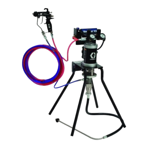
For low-volume fine finish spray applications. For professional use only.
Important Safety Instructions
Read all warnings and instructions in
this manual. Save these instructions.
15:1 Spray Packages
30:1 Spray Packages
100 psi (0.7 MPa, 7.0 bar) Maximum Air Inlet Pressure
See page 3 for model information, including maximum fluid
working pressure.
®
ES Spray
ti15589a
3A0732U
EN
ti15590a
II 2 G Ex h T5 Gb X
Advertisement
Table of Contents

Related Manuals for Graco Merkur ES


Summary of Contents for Graco Merkur ES
- Page 1 Instructions/Parts ® Merkur ES Spray Packages 3A0732U For low-volume fine finish spray applications. For professional use only. Important Safety Instructions Read all warnings and instructions in this manual. Save these instructions. 15:1 Spray Packages 30:1 Spray Packages 100 psi (0.7 MPa, 7.0 bar) Maximum Air Inlet Pressure See page 3 for model information, including maximum fluid working pressure.
-
Page 2: Table Of Contents
Graco Standard Warranty....50 Graco Information......50... -
Page 3: Models
Models Models Maximum Fluid Package Series Ratio Working Pressure Package Type Gun Mounting Material psi (MPa, bar) 24F150 15:1 1500 (10.3, 103) Air-assisted PerformAA 15 Wall Plated Steel 24F151 15:1 1500 (10.3, 103) Air-assisted PerformAA 15 Stand Plated Steel 24F152 30:1 3000 (20.7, 207) Air-assisted... -
Page 4: Warnings
Warnings Warnings The following warnings are for the setup, use, grounding, maintenance, and repair of this equipment. The exclamation point symbol alerts you to a general warning and the hazard symbols refer to procedure-specific risks. When these symbols appear in the body of this manual, refer back to these Warnings. Product-specific hazard symbols and warnings not covered in this section may appear throughout the body of this manual where applicable. - Page 5 Warnings WARNING SKIN INJECTION HAZARD High-pressure fluid from gun, hose leaks, or ruptured components will pierce skin. This may look like just a cut, but it is a serious injury that can result in amputation. Get immediate surgical treatment. • Do not spray without tip guard and trigger guard installed.
- Page 6 Warnings WARNING TOXIC FLUID OR FUMES HAZARD Toxic fluids or fumes can cause serious injury or death if splashed in the eyes or on skin, inhaled, or swallowed. • Read Safety Data Sheets (SDSs) to know the specific hazards of the fluids you are using. •...
-
Page 7: Installation
Installation Installation Prepare the Operator • The air pressure relief valve (P) opens automatically to prevent overpressurization of the pump. All persons who operate the equipment must be trained in the safe, efficient operation of all system components • The gun air regulator (E) adjusts the air pressure as well as the proper handling of all fluids. -
Page 8: Wall Mount Packages
Installation Wall Mount Packages 1. Be sure the wall can support the weight of the pump, bracket, hoses and accessories, as well as the stress caused during operation. 2. Position the wall bracket at a convenient height. Do not stretch the suction hose tight; let it hang to assist fluid flow into the pump. -
Page 9: Setup
Installation Setup 1. See F . 2. Attach one end of fluid hose (K) to pump 4. Attach remaining end of the air hose to air inlet at outlet (or optional inline fluid filter outlet). base of gun (H). 2. Attach other end of fluid hose to gun fluid inlet at 5. -
Page 10: Operation
Operation Operation Pressure Relief Procedure Trigger Lock Trapped air can cause the pump to cycle See F . 3. Always engage gun trigger lock when you unexpectedly, which could result in serious injury stop spraying to prevent gun from being triggered from skin injection, splashing or moving parts. -
Page 11: Install The Spray Tip
Operation Adjust the Atomization 3. Connect air line to bleed type air valve. 4. Check that all fittings throughout system are tightened securely. 5. Position pail close to pump. Suction hose is 3 ft (0.9 m) long. Do not stretch hose tight; let it hang to NOTE: Use this procedure with airless and air-assisted assist fluid flow into pump. -
Page 12: Adjust The Spray Pattern
Operation Adjust the Spray Pattern 2. See F . 5. Set atomizing air pressure at about 5 psi (0.35 bar, 35 kPa) when triggered. Check spray pattern, then slowly increase air pressure until tails are completely atomized and pulled into spray pattern. -
Page 13: Maintenance
At the end of the day 9. Clean inside and outside of suction tube and • Before storing the pump. suction hose. Wet Cup Fill wet cup one-half full with Graco Throat Seal Liquid (TSL). Maintain TSL level daily. 3A0732U... -
Page 14: Troubleshooting
ID is too small. Fluid dried on the displacement rod Clean; keep the packing nut (119). wet-cup filled with Graco throat seal liquid (TSL). Pump operates but does not Held open or worn ball check valves Clear valve; replace packings. See prime. - Page 15 Troubleshooting Problem Cause Solution Pump operates, but output is low Held open or worn ball check valves Clear valve; replace packings. See on downstroke. or piston packings. page 17. Erratic or accelerated pump Exhausted fluid supply. Refill and prime. speed. Held open or worn ball check valves Clear valve, replace packings.
-
Page 16: Repair
• Always use Genuine Graco Parts and Accessories, available from your Graco distributor. If you supply 1. Stop the pump. your own accessories, be sure they are adequately sized and pressure rated for your system. -
Page 17: Disassemble The Pump
Repair Disassemble the Pump c. Install the male gland (122‡) onto the rod. NOTE: Pump Repair Kits are available. See page 42. d. Install the piston wiper (123‡) onto the piston Parts are marked with an ‡. (124). 1. Follow the instructions under Disconnect the Displacement Pump, page 16. - Page 18 Repair Install Throat Packings U-Cup Models (24J250 and 24J251): F . 10 a. Install the u-cup (128) with the lips facing down Install the throat packings in the cylinder (105). and the bushing (127) onto the rod (119). V-Packing Models: F a.
-
Page 19: Reconnect The Displacement Pump
Repair Reconnect the Displacement 4. Follow the Reconnect the Reconnect the Displacement Pump, pg 19. Pump NOTICE The displacement pump can be damaged if the stroke is not centered when the pump is recon- nected. Be sure to fully screw the displacement pump into the adapter plate (10). - Page 20 Repair NOTE: Air Valve Seal Kits are available. See page 39. Parts are marked with an †. Air Valve Repair Kits are available. See page 39. Parts are marked with an ◆. Air Valve End Cap Kits are available. See page 39. Parts are marked with an ✚.
- Page 21 Repair † 306 † 308 † 309 † 308 † 306 ti16213a Apply lubricant. . 13. Air Valve Assembly 3A0732U...
-
Page 22: Replace Pilot Valves
Repair Reassemble the Air Valve 7. Install the spring (311◆). Lubricate and install the air valve cup (312◆), see F . 15. Align the small 1. See F . 13. Lubricate detent cam (304◆) and round magnet with the air inlet. install into housing. -
Page 23: Disconnect The Air Motor
Repair Disconnect the Air Motor 1. Stop the pump. 2. Flush the pump, if possible (see page 13). Follow Pressure Relief Procedure, page 10. 3. Disconnect the air hose, fluid hose, and suction hose. 4. See F . 16. Push the safety spring (9) down and hold to access the coupling pin (18). -
Page 24: Repair Air Motor
Repair Repair Air Motor 9. Remove the rod from the bottom cover assembly. 10. Remove retaining ring (217), u-cup seals (207*), and o-ring (202*) from the bottom cover. NOTE: Complete Air Motor Replacement Kits are Reassemble the Air Motor available. Order 24G693 (2.5 in. motor) or 24G694 (3.5 in. - Page 25 Repair Apply lubricant. 204* *230 208* 202* *202 *217 *207 209* † 208* *207 TI16130a . 18. Air Motor Assembly 5. Lubricate and install the o-ring (202*) on the bottom 7. Apply 16G561 adhesive to the threads of the rod cover (201).
- Page 26 Repair 9. See F . 19. Carefully place the bottom 10. Install the tie bolts (212) hand tight. cover/piston assembly on the cylinder (205), sliding 11. Install two gaskets (208*) on the manifold (220). the piston (219) into the cylinder. The manifold Install the manifold (220).
-
Page 27: Parts
Parts Parts Package Parts NOTE: For hose and gun, see page 32. Part of air motor (7) Detail of Stand Kit (2) 1 (Ref) TI16438a TI16129a 3A0732U... - Page 28 162453 162453 162453 1 npsm x 1/4 npt; plated steel NIPPLE; 1/4 166846 166846 166846 npsm x 1/4 npt; ‡ Included in Pump Lower Rebuild Kit. See page 33. * Not shown. See Merkur ES Hopper Kit manual 334011 for more information. 3A0732U...
- Page 29 15E813 15E813 15E813 1 suction WASHER, lock; 1/4; part of stand kit (2) 44* HOPPER, kit 17A493 17A493 ‡ Included in Pump Lower Rebuild Kit. See page 33. * Not shown. See Merkur ES Hopper Kit manual 334011 for more information. 3A0732U...
- Page 30 116343 116343 116343 116343 116343 116343 116343 116343 WIRE, grounding 238909 238909 238909 238909 238909 238909 238909 238909 ‡ Included in Pump Lower Rebuild Kit. See page 42. * Not shown. See Merkur ES Hopper Kit manual 334011 for more information. 3A0732U...
- Page 31 15E813 15E813 15E813 15E813 WASHER, lock; 1/4; part of stand kit (2) HOPPER, kit 17A493 17A493 1 ‡ Included in Pump Lower Rebuild Kit. See page 42. * Not shown. See Merkur ES Hopper Kit manual 334011 for more information. 3A0732U...
-
Page 32: Hose And Gun
Parts Hose and Gun Air-Assisted Packages Airless Packages TI16231a TI16230a 24F150 24F158 24F152 24F156 Ref. 24J250 24F154 Description 24F151 24F159 24F153 24F157 24X311* 24J251 24F155 24W281 24W283 24W287 24W285 HOSE, air, gun 241811 241811 241811 241811 241811 GUN, air-assisted, 26B500 26B500 25B502 PerformAA 15, see manual... - Page 33 Parts Displacement Pump Parts Part No. 24G701, Plated Steel, V-Packing Part No. 24G702, Stainless Steel, V-Packing ‡102 ‡121 ‡104 ‡112 125‡ ‡126 ‡122 ‡106 ‡123 113‡ ‡120 ‡114 15, see page 28 109❖ 116 ‡❖ 117❖✖ 111‡❖✖ 107‡✖ ti32016a 3A0732U...
- Page 34 Parts Displacement Pump Parts Part No. 24J121, Plated Steel, U-Cup ‡102 129✖ 127✖ 130 ✖ 128✖ 120 ‡ 15, see page 28 109 ❖ 116 ‡❖ 117❖✖ 107‡✖ 111‡❖✖ 3A0732U...
- Page 35 Parts Displacement Pump Parts Part No. 24G701, Plated Steel, V-Packing Part No. 24G702, Stainless Steel, V-Packing Part No. 24J121, Plated Steel, U-Cup Ref. Description 24G701 24G702 24J121 102‡ BUTTON, plug NUT, packing; plated steel 193047 193047 NUT, packing; sst 24H161 104‡...
-
Page 36: Air Motor Parts
Parts Air Motor Parts Part No. 24G693, 2.5 in. (63.5 mm) Part No. 24G694, 3.5 in. (88.9 mm), shown 204* *230 208* 202* *202 *217 *207 209*◆† 208* *207 TI16130a 3A0732U... - Page 37 Parts Air Motor Parts Part No. 24G693, 2.5 in. (63.5 mm) Part No. 24G694, 3.5 in. (88.9 mm), shown Ref. Description 24G693 24G694 KIT, cover, bottom; includes 202 (qty 1), 24G695 24G696 203, 207, 213 (qty 1), and 217 202* O-RING, cover Not sold separately.
-
Page 38: Air Valve Parts
Parts Air Valve Parts ✚ 310 †✚◆306 ✚ 307 ◆ 304 ◆ 303 ◆ 311 ◆ 312 ◆ 305 †◆ 308 ◆ 302 †◆ 309 †◆ 308 ✚ 307 †✚◆306 ti16213a ✚ 310 3A0732U... - Page 39 Parts Air Valve Parts Complete Air Valve Replacement Kit 24A351 To replace the complete air valve, order Air Valve Replacement Kit 24A351. The kit includes items 301-312 below, and items 209 and 211 on page 37. Air Valve Repair Kits Air valve parts are not sold individually.
-
Page 40: Air Control Parts
Parts Air Control Parts Part No. 24H162, Air-Assisted, Wall Mount Part No. 24H163, Air-Assisted, Stand Mount Part of 402 TI16132a Connect tubing (406) between these two fittings. Used on stand mount units only. Part No. 24H164, Airless, Wall Mount Part No. 24H165, Airless, Stand Mount Connect tubing (406) between these two fittings. - Page 41 Parts Air Control Parts Part No. 24H162, Air-Assisted, Wall Mount Part No. 24H163, Air-Assisted, Stand Mount Part No. 24H164, Airless, Wall Mount Part No. 24H165, Airless, Stand Mount Description 24H162 24H163 24H164 24H165 Qty BRACKET, handle 24H105 24H105 24H105 24H105 REGULATOR, air 15T499 15T499...
-
Page 42: Kits And Accessories
Kits and Accessories Kits and Accessories Kit Description Part No. Airless to Air-Assisted Conversion Kit 24F161 Inline Fluid Filter, stainless steel 24F271 Inline Fluid Filter, aluminum 24F272 24F148 Standard Suction Hose, 5 gal. (19 l), 3/8 in. (10 mm) OD 24F149 Suction Hose, 5 gal. -
Page 43: Package Dimensions
Package Dimensions Package Dimensions A, inch B, inch C, inch D, inch Package (mm) (mm) (mm) (mm) 20.2 (513) Wall Mount 29.0 (737) 17.4 (442) 18.4 (467) Stand Mount 29.0 (737) 17.4 (442) 26.5 (673) Stand Mount with Hopper Front View Top View ti16288a ti16287a... -
Page 44: Package Weights
Package Weights Package Weights Package Description lb kg 20 9 24F150 15:1 plated steel, AA, wall 23 10 24F151 15:1 plated steel, AA, stand 23 10 24F152 30:1 stainless steel, AA, wall 26 12 24F153 30:1 stainless steel, AA, stand 22 10 24F154 30:1 plated steel, airless, wall... -
Page 45: Wall Bracket Mounting Hole Diagram
Wall Bracket Mounting Hole Diagram Wall Bracket Mounting Hole Diagram 2 x 0.35 in. (9 mm) 2 x 0.281 (9/32) in. (7 mm). For wall mount only. 4.40 in. (112 mm) 2.69 in. (68 mm) 2 x 0.62 in. (16 mm) 2 x 0.48 in. -
Page 46: Technical Data
Technical Data Technical Data Maximum fluid working pressure 15:1 Pumps 1500 psi (10.3 MPa, 103 bar) 30:1 Pumps 3000 psi (20.7 MPa, 207 bar) Maximum air inlet pressure 100 psi (0.7 MPa, 7.0 bar) 15:1 or 30:1 (see Models, page 3) Ratio Maximum fluid temperature. -
Page 47: Performance Charts
Performance Charts Performance Charts 15:1 Ratio Pumps A = 100 psi (0.7 MPa, 7 bar) B = 70 psi (0.5 MPa, 5 bar) C = 40 psi (0.3 MPa, 3 bar) = fluid flow = air flow Cycles per Minute 1400 10.5 (10, 100) -
Page 48: 30:1 Ratio Pumps
Performance Charts 30:1 Ratio Pumps A = 100 psi (0.7 MPa, 7 bar) B = 70 psi (0.5 MPa, 5 bar) C = 40 psi (0.3 MPa, 3 bar) = fluid flow = air flow Cycles per Minute 3000 18.0 (21, 210) (0.5) 2500... -
Page 49: California Proposition 65
California Proposition 65 California Proposition 65 CALIFORNIA RESIDENTS WARNING: Cancer and reproductive harm. – www.P65warnings.ca.gov. 3A0732U... -
Page 50: Graco Standard Warranty
With the exception of any special, extended, or limited warranty published by Graco, Graco will, for a period of twelve months from the date of sale, repair or replace any part of the equipment determined by Graco to be defective.
Need help?
Do you have a question about the Merkur ES and is the answer not in the manual?
Questions and answers