Table of Contents
Advertisement
Quick Links
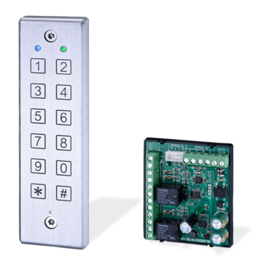
DG-187
Digital Keypad Separated Controller System
Operation Manual
Features:
1. Epoxy sealed for waterproof function (IP65).
2. Designed with piezoelectric keypad.
3. Built-in light sensor detection switch for vandal resistance.
4. Digital keypad separated control system designed to enhance security.
5. Aluminum alloy casing with vandal resistant screws for enhanced safety and durability.
6. Allows up to 1000+10 PINs.
7. The controller will be locked for 60 seconds upon 5 consecutive invalid PINs.
8. Controller with keypad sound to avoid incorrect key-in.
9.
Additional input for anti-tailgating function to ensure high security access control.
10. Non-volatile memory control can retain all PIN codes in event of power failure.
11.
Dual relays for electric lock devices and other access control systems.
Specifications
Operating Voltage
LED Status Indication
Relay Strike Time
Ambient Humidity
Operating Temperature
Status Indications & Default Setting Parameters
Beep & LED Indications:
Unit:mm
LED
Beep
12~24VAC/VDC
Pull in: 120mA/12 VDC
Current Draw
Pull in: 70mA/24 VDC
Keypad
6X2 matrix keypad
2 contacts for Request-To-Exit buttons
Input
1 contact for Door Status Sensor
1 contact for Anti-Tamper Alarm Tamp (-)
Output
2 relays (N.O./COM./N.C.)
2 LEDs – 4 Colors (Blue/Green/Yellow/Red)
Memory Volume
1000+10 PINs
Max. 3A/30 VDC
Relay Rating
01~99 seconds or manual mode(00)
5%~95% (Non-condensing)
-20 C~60 C
Mode
Signal
Blue Indicator On
Power on, Standby
Standby
Green Indicator On
First Relay Activated
Red Indicator On
Second Relay Activated
Yellow Indicator On Programming Mode Entry
Green Indicator On
The slot position of first relay is available
Programming
Red Indicator On
The slot position of first relay is unavailable
Green Indicator On
The slot position of second relay is available
Red Indicator On
The slot position of second relay is unavailable
1 Beep
Key entry, and Enter Programming mode
Standby
2 Beeps
Incorrect PIN
1 Beep
Correct input data, and Exit Programming mode
Programming
3 Beeps
Incorrect input data or Other invalid operation
;
Holding: 60mA/12 VDC
;
Holding: 40mA/24 VDC
(0~9 ,
, #)
Status
Advertisement
Table of Contents

Related Manuals for Gianni DG-187


Summary of Contents for Gianni DG-187
-
Page 1: Specifications
Specifications DG-187 12~24VAC/VDC Operating Voltage Pull in: 120mA/12 VDC ; Holding: 60mA/12 VDC Current Draw Pull in: 70mA/24 VDC ; Holding: 40mA/24 VDC Digital Keypad Separated Controller System (0~9 , , #) Keypad 6X2 matrix keypad Operation Manual 2 contacts for Request-To-Exit buttons... -
Page 2: Wiring Diagrams
Press # (1 beep ) to be back to Standby Mode (Blue LED is on). NOTE: For both Relay 1 & Relay 2, entering 00 will set relay strike time to 0 second. DG-187 N.O. Entering 05 indicates 5 seconds and so on. - Page 3 Press # (1 beep) to be back to Standby Mode (Blue LED is on). 10. Turning Lock-out Function ON/OFF (Default setting is ON) a. Enter Programming Mode. Copyright © All Rights Reserved. P-MU-DG-187 Published: 2015.05.21 b. Press 7 (Yellow LED flashes).
Need help?
Do you have a question about the DG-187 and is the answer not in the manual?
Questions and answers