Table of Contents
Advertisement
Quick Links
HDMI, DISPLAY PORT INTERFACE CONTROLLER
CONTENTS
Page: 2. Introduction, How to Proceed, Usage Note, Disclaimer
3. System design – Diagram of a suggested system
4. Assembly notes – Important information about system elements
6. Connection & Operation – How to use the controller
10. Connectors, pinouts & jumpers – Essential connection information
18. Controller dimensions
19. Application notes
20. Troubleshooting
21. Specifications
23. Appendix I – Mode Support Table
24. Appendix II – RS-232 control protocols
28. Appendix III – DDC/CI support at HDMI & Display port
29. Appendix IV – Mapping definition
33. Appendix V – DV remote control unit work for ALR-1920-120
34. Warranty, Caution & Limitation of Liability, Trademarks
35. Contact details
It is essential that these instructions are read and understood before connecting or
powering up this controller.
FOR TFT PANEL
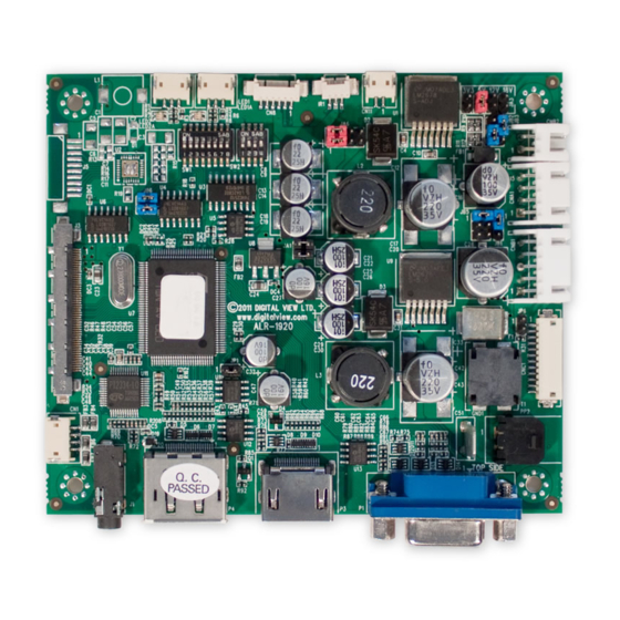
Model: ALR-1920-120
Part number : 41731003X-3 or up
INSTRUCTIONS
Advertisement
Table of Contents

Subscribe to Our Youtube Channel
Related Manuals for Digital View ALR-1920-120


Summary of Contents for Digital View ALR-1920-120
- Page 1 24. Appendix II – RS-232 control protocols 28. Appendix III – DDC/CI support at HDMI & Display port 29. Appendix IV – Mapping definition 33. Appendix V – DV remote control unit work for ALR-1920-120 34. Warranty, Caution & Limitation of Liability, Trademarks 35. Contact details It is essential that these instructions are read and understood before connecting or powering up this controller.
- Page 2 Introduction ALR-1920-120 is the controller board equipped with IE-1010 and ALR-1920 engine integrated. ALR-1920-120 is capable to drive the panel up to 1920x1200 resolution and also supporting up to 120Hz panel. This controller supports HDMI and Display Port input. And it will be the lower cost solution for 120Hz panel.
-
Page 3: System Design
14. SPDIF Audio output 15. Panel backlight control (for 120Hz panel used only) 16. Power input (12VDC / 24VDC) Digital View offers a range of accessories such as listed above, to make up complete display solution. Page 3 of 35... -
Page 4: Assembly Notes
ASSEMBLY NOTES ALR-1920-120 is the controller board equipped with IE-1010 and ALR-1920 engine integrated. ALR-1920-120 is capable to drive the panel up to 1920x1200 resolution and also supporting up to 120Hz panel. This controller supports HDMI and Display Port input. And it will be the lower cost solution for 120Hz panel. - Page 5 • EMI: Shielding will be required for passing certain regulatory emissions tests. Also the choice of external Controller to PC signal cable can affect the result. • Ground: The various PCB mounting holes are connected to the ground plane. • Servicing: The board is not user serviceable or repairable.
-
Page 6: Connection And Operation
CONNECTION & OPERATION CAUTION: Never connect or disconnect parts of the display system when the system is powered up as this may cause serious damage. CONNECTION Connection and usage is quite straight forward (it is useful to have the relevant connection diagram available at this time): LCD panel &... - Page 7 BUTTONS & DEMO MODES • Button switch – TS2 : Push TS2 to cycle between the 4 different demo modes (This function is activated when JP3 sets OPEN only) Mode 1 (default) = RIGHT demo mode, right side of screen with smoothed motion while left side without (a box with yellow border appear on RIGHT hand side of screen);...
- Page 8 LCD DISPLAY SYSTEM SETTINGS NOTE: By way of explanation the following refers to a set of sample buttons that may be obtained as an option. In addition to power on/off and connection for backlight brightness the controller provides an On Screen Display of certain functions which are controlled by 5 momentary type buttons (analog VR type) or 8 momentary type buttons (digital type): Controls Analog VR type...
- Page 9 OSD Functions Image Increase/decrease brightness level. Brightness Press – or + (- + ) Total : 100 steps Increase/decrease contrast level. Contrast Press – or + (- + ) Total : 100 steps Increase/decrease sharpness level. Sharpness Press – or + (- + ) Total : 8 steps Color Color temp4 (Adjust the warmness of the image displayed.
-
Page 10: Connectors, Pinouts & Jumpers
CONNECTORS, PINOUTS & JUMPERS The various connectors are: Summary: Connectors Purpose Description Audio output (Stereo) with amplication JST 4-way, S4B-ZR-SM4A (Mating type : ZHR-4) from HDMI / Display port (Matching connection cable P/N 426685400-3) Serial control Molex 53261-0671, 6 ways 1.25mm pitch (Mating type : Molex 51021-0600) (Matching connection cable P/N 426171800-3) CN11... - Page 11 Summary: Jumpers setting Purpose Note On board +1V logic power enable 1-3 & 2-4 closed, factory set, do not remove On board +5V logic power enable 1-2 & 3-4 closed, factory set, do not remove Panel power voltage select See panel voltage setting table 1 CAUTION: Incorrect setting will cause panel damage Panel power voltage select See panel voltage setting table 1...
- Page 12 Input voltage via Panel Voltage Jumper on board 3.3V 3V3 closed 1-3 & 2-4 5V closed 1-3 & 2-4 24VDC** 12V closed 3-5 & 4-6 18V closed 3-5 & 4-6 ** Please make sure the backlight inverter must support 24V supply. Because CNA1 pin 1 and CNB1 pin 2 will output 24VDC if input 24VDC via PP2.
- Page 13 Pos #3 Pos.#4 Description Panel resolution For WUXGA panel Samsung LTM220CS01 1920x1200 AU Optronics M215HW01 V0 1920x1080 For SXGA panel Fujitsu FLC48SXC8V-11AA 1280x1024 For additional and recent added panels, see ALR-1920-120 panel support table at http://www.digitalview.com/controllers/csg.php Page 13 of 35...
- Page 14 CN1 – Audio output (Stereo) with amplication from HDMI / Display port : JST 4-way, S4B-ZR-SM4A (Mating type : ZHR-4) SYMBOL DESCRIPTION AMP L- Audio Left channel (Negative) AMP L+ Audio Left channel (Positive) AMP R- Audio Right channel (Negative) AMP R+ Audio Right (Positive) CN8 –...
- Page 15 J2 – LVDS output connector: JAE FI-RE41S-HF (Matching type : JAE FI-RE41HL) SYMBOL DESCRIPTION Ground LVDS_OUT2_B0- Negative differential LVDS data bit B0 LVDS_OUT2_B0+ Positive differential LVDS data bit B0 LVDS_OUT2_B1- Negative differential LVDS data bit B1 LVDS_OUT2_B1+ Positive differential LVDS data bit B1 LVDS_OUT2_B2- Negative differential LVDS data bit B2 LVDS_OUT2_B2+...
- Page 16 J3 – LVDS output connector: JAE FI-RE51S-HF (Matching type : JAE FI-RE51HL) SYMBOL DESCRIPTION VLCD_HV Panel power supply (+12V / 18V) (selected by JA3 & JA6) VLCD_HV Panel power supply (+12V / 18V) (selected by JA3 & JA6) VLCD_HV Panel power supply (+12V / 18V) (selected by JA3 & JA6) VLCD_HV Panel power supply (+12V / 18V) (selected by JA3 &...
- Page 17 LED1 – Dual color LED connector for controller status, JST 3-way, S3B-ZR-SM4A (Mating type : JST ZHR-3) DESCRIPTION Green LED pin (anode) LED pin common (cathode) Red LED pin (anode) P3 – HDMI connector SYMBOL DESCRIPTION DATA2+ TMDS Data2+ DATA2S TMDS Data2 Shield DATA2- TMDS Data2–...
-
Page 18: Controller Dimensions
CONTROLLER DIMENSIONS The maximum thickness of the controller is 17.3mm (measured from bottom of PCB to top of components, including any underside components & leads). We recommend clearances of: • 5mm from bottom of PCB - if mounting on a metal plate we also recommend a layer of suitable insulation material is added to the mounting plate surface. -
Page 19: Application Notes
APPLICATION NOTES USING THE CONTROLLER WITHOUT BUTTONS ATTACHED This is very straightforward by following the steps below : • Firstly setup the controller/display system with the buttons. With controls attached and display system active make any settings for colour and image position as required then switch everything off. •... - Page 20 Design Guideline for making VR circuitry : Signal description / Notes : 1) R1 : 470ohm on board 2) RPOT is an external potentiometer (in-line dip style) that can be plugged directly into CNC1 pins 3,4,5. RPOT must be supplied / installed by user. 3) BVR_B : Voltage tapped from “top”...
-
Page 21: Troubleshooting
TROUBLESHOOTING General A general guide to troubleshooting a flat panel display system it is worth considering the system as separate elements, such as: Controller (jumpers, PC settings) Panel (controller, cabling, connection, panel, PC settings) Backlight (inverter, cabling, backlight tubes) Cabling Computer system (display settings, operating system) Through step by step cross checking with instruction manuals and a process of elimination to isolate the problem it is usually possible to clearly identify the problem area. -
Page 22: Specifications
SPECIFICATIONS Panel compatibility Compatible with 120Hz panel with 1920x1200, 1920x1080 resolutions. A specified BIOS and some factory adjustment may be required for individual panel timings. No. of colours Up to 10 bit per color, providing 1.07 billion colours. Vertical refresh rate WUXGA, UXGA, WXGA, SXGA, XGA, SVGA, VGA resolution up to 120Hz. -
Page 23: Appendix I - Mode Support Table
Appendix I – Mode Support Table HDMI (P3) port : Mode Resolution Clk [MHz] Horizontal Vertical freq [KHz] freq [Hz] T_70 720x400 70Hz 28.322 31.469 70.087 V_60 640x480 60Hz 25.175 31.469 59.940 SV_60 800x600 60Hz 40.000 37.879 60.317 X_60 1024x768 60Hz 65.000 48.363 60.004... -
Page 24: Appendix Ii - Rs-232 Control Protocols
Appendix II – RS-232 control protocols 8 bits, 1 stop bit and no parity RS-232 Serial control (Baud rate 2400, Physical connection : Controller side Computer side Connector interface : CN8 Connector interface : Serial port Mating connector : Molex 51021-0600 Mating connector : DB9 Female Mating face of CN8 Mating face of RS-232 DB9 Male... - Page 25 OSD V position 0x91, Set osd_vpos = OSD vertical position nnn | “+” | “-“ | “r” | value/increment/decrement “R” | “?” Reset Range: “0””0””0”-“3””E””8” Query Default: “1””F””4” Select menu 0x93, Select menu timeout = OSD menu timeout value. timeout nn | “+”...
- Page 26 Read BIOS version “nnnn” = BIOS ver. “nn.nn” version Query PCBA 0xcb, “1” Read PCBA number “nnnn” = PCBA number number ALR-1920-120=”41731” Load factory 0xce Reset all parameters to factory “1” – successful. defaults default value Page 26 of 35...
- Page 27 Hex to ASCII conversion table ASCII ASCII ASCII ASCII 0x30 0x41 0x61 0x2B 0x31 0x42 0x62 0x2D 0x32 0x43 0x63 0x3F 0x33 0x44 0x64 0x34 0x45 0x65 0x35 0x46 0x66 0x36 0x47 0x67 0x37 0x48 0x68 0x38 0x49 0x69 0x39 0x4A 0x6A 0x4B...
-
Page 28: Appendix Iii - Ddc/Ci Support At Hdmi & Display Port
Appendix III – DDC/CI support at HDMI & Display port This controller supports the following DDC/CI commands at HDMI & Display port : Brightness Contrast RGB Color Input Source (HDMI & Displayport) Power States (On, Standby, Sleep) • On mode: Always on. Display No sync message and never goes off when no signal •... -
Page 29: Appendix Iv - Mapping Definition
Appendix IV – Mapping definition • Definition of Mapping A : Page 29 of 35... - Page 30 • Definition of Mapping B : Page 30 of 35...
- Page 31 • Definition of VESA : Page 31 of 35...
- Page 32 • Definition of JEIDA : Page 32 of 35...
-
Page 33: Appendix V - Dv Remote Control Unit Work For Alr-1920-120
Appendix V – DV remote control unit work for ALR-1920-120 P/N 559000106-3 : DigitalView remote control unit (without DV logo silk screen printing) P/N 559000105-3 : DigitalView remote control unit (with DigitalView logo silk screen printing) BUTTON FUNCTION POWER BUTTON Soft power ON/OFF button. -
Page 34: Warranty
The manufacturer’s liability for damages to customer or others resulting from the use of any product supplied hereunder shall in no event exceed the purchase price of said product. TRADEMARKS The following are trademarks of Digital View Ltd: • Digital View •... -
Page 35: Contact Details
CONTACT DETAILS Digital View has offices in Asia, Europe and USA also an internet site: ASIA Digital View Ltd Floor Millennium City 3 370 Kwun Tong Road Kwun Tong Hong Kong Tel: (852) 2861 3615 Fax: (852) 2520 2987 Sales: hksales@digitalview.com...
Need help?
Do you have a question about the ALR-1920-120 and is the answer not in the manual?
Questions and answers