Advertisement
Table of Contents
- 1 Table of Contents
- 2 Specifications and Requirements
- 3 Warnings and Cautions
- 4 Maintenance and Warranty
- 5 Installation
- 6 User Instructions
- 7 Outside Mount (Optional)
- 8 Component and Wiring Diagram
- 9 Ladder Type Schematic Diagram
- 10 Servicing Instructions
- 11 Pipe Sizing Guidelines
- 12 Parts & Assemblies
- Download this manual
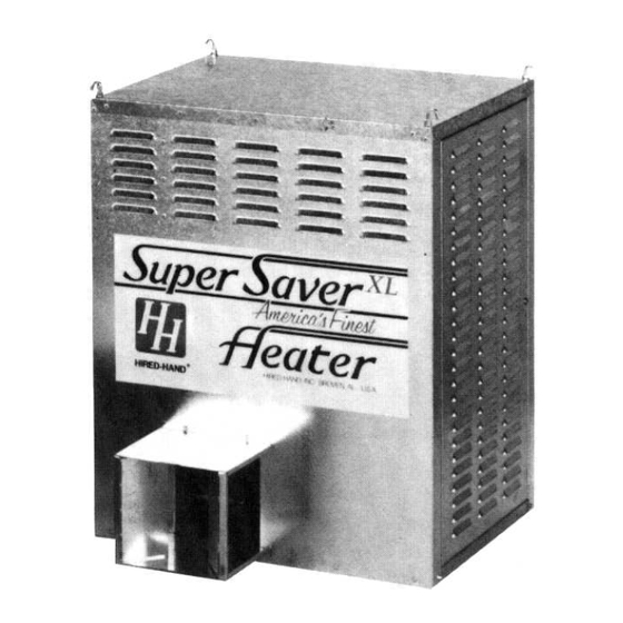
SUPER-SAVER XL
MODEL
SS-225-XL-120
FOR YOUR SAFETY
If you smell gas:
1. Open windows
2. Don't touch electrical switches
3. Extinguish any open flames
4. Immediately call your gas supplier
CONSIGNES DE SECURITE
Si vous sentez une odeur de gaz:
1. Ouvrez les fenetres
2. Ne touchez pas aux interrupteurs electriques
3. Etegnex toute flamme hue
4. Contactez immediatement votre compangie
de gaz
HIRED-HAND, INC. • 1733 County Road 68 • Bremen, AL 35033 USA• Phone 256-287-1000 • Fax 256-287-2000
Owner's Manual
Agricultural Building Heater – Direct Spark Igniter
BTUH
kW
225,000
65.9
Retain Instructions For Future Reference
Manual Part No. 4801-3031 Rev 6-09
TM
♦
Direct Spark Ignition
FOR YOUR SAFETY
Do not store or use gasoline or any
flammable vapors and liquids in the
vicinity of this or any other appliance
CONSIGNES DE SECURITE
II es interdit d'utiliser des liquides
inflammables ou degageant des
vapeurs inflammables, a proximite
de tout appareil fonctionnant au gaz
HEATER
♦
Wash Down Design
Advertisement
Table of Contents

Related Manuals for HIRED-HAND SUPER-SAVER XL SS-225-XL-120


Summary of Contents for HIRED-HAND SUPER-SAVER XL SS-225-XL-120
- Page 1 4. Contactez immediatement votre compangie de tout appareil fonctionnant au gaz de gaz Retain Instructions For Future Reference HIRED-HAND, INC. • 1733 County Road 68 • Bremen, AL 35033 USA• Phone 256-287-1000 • Fax 256-287-2000 Manual Part No. 4801-3031 Rev 6-09...
- Page 2 GENERAL HAZARD WARNING Failure to comply with precautions and instructions provided with this heater can result in death, serious bodily injury and property loss or damage from hazards of fire, explosion, burn, asphyxiation, carbon monoxide poisoning, and/or electrical shock. If you need assistance or heater information such as an instruction manual, labels, etc.
-
Page 3: Table Of Contents
Outside Mount (Optional).......9 all of the listed parts are enclosed. Component And Wiring Diagram ....10 Ladder Type Schematic Diagram ....11 not, call your Hired-Hand Servicing Instructions........12 Distributor immediately. Pipe Sizing Guidelines.........17 Parts & Assemblies........19 HEATER DIMENSIONS WEIGHT 130 lb. (60 kg) -
Page 4: Specifications And Requirements
Warnings and Cautions WARNING When Heater Is Connected To Remote Thermostat Heater May Start At Any Time! ELECTRICAL GROUNDING INSTRUCTIONS This appliance requires a three prong (grounding) plug for your protection against electrical shock and should be plugged directly into a properly grounded three-prong receptacle. C A U T I O N ! Installation must comply with all local, state, and national codes. -
Page 5: Maintenance And Warranty
This appliance rating is based on the use of ANSI LC-2 test gases including LP (2500 BTU/ft 93.15 MJ/m ) and natural gas (1075 BTU/ft , 40 MJ/m ). Hired-Hand, Inc. makes no guarantees regarding the proper operation of this appliance when these conditions are not met. Part No. 4801-3031 Rev.6-09 Page... - Page 6 Limited Warranty Warranty The GSI Group, LLC. (“GSI”) warrants products which it manufactures to be free of defects in materials and workmanship under normal usage and conditions for a period of 12 months after sale to the original end-user or if a foreign sale, 14 months from arrival at port of discharge, whichever is earlier.
-
Page 7: Installation
Installation 5.1 Hanging The Heater Chain Suspension Cable Suspension Mount heater with screw hooks and chains so that back of heater is at least 12 inches (305 mm) from If frequent height adjustment is required, use ceiling and wall. Heater must be a minimum of 20 cables and pulleys. -
Page 8: User Instructions
User Instructions Before turning on gas, check main supply valve to be sure it is open (Fig. 3). Be sure to check all connections for leaks with a Gas Leak Testing solution, (soap and water work well). Check to see if gas valve knob is in the ON position. -
Page 9: Outside Mount (Optional)
Outside Mount (Optional) Hired-Hand heaters are available in Outside Mount (OSM) models. These heaters are designed to be mounted to the outside wall of a building. This saves valuable space inside the building and ensures fresh air intake for the heater. -
Page 10: Component And Wiring Diagram
Component and Wiring Diagram COMPONENT AND WIRING DIAGRAM CONTROL BOX THERMOSTAT OPTIONS Low Voltage Control Piggy-Back Direct Wire Thermostat Thermostat or Controller REMOVE JUMPER FOR DIRECT WIRE THERMOSTAT OPTION INSIDE HEATER 120 Volts A.C. 50/60 Hz Single Phase Part No. 4801-3031 Rev.6-09 Page Super Saver XL-120 Heater... -
Page 11: Ladder Type Schematic Diagram
Ladder Type Schematic Diagram LADDER TYPE SCHEMATIC DIAGRAM LINE VOLTAGE NEUTRAL GROUND THERMOSTAT LINE VOLTAGE ON / OFF LOW LINE 10 AMP FUSE TRANSFORMER 24 VAC-40VA, 50/60 Hz UNITED TECHNOLOGIES Direct Spark Ignition Control SAIL SWITCH MAIN REDUNDANT VALVE VALVE FLAME SENSOR HIGH LIMIT PROBE... -
Page 12: Servicing Instructions
Servicing Instructions 10.1 United Technologies Direct Spark Ignition System IMPORTANT! Inspect and check operation of this appliance monthly. Follow the instructions below. If a problem is detected, contact a qualified technician to make any necessary repairs. In an effort to minimize the time required to trouble shoot this system: Turn off the gas supply at the main gas valve. - Page 13 10.2 1016 Direct Spark Ignition Status Indicator Error Conditions The status indicator LED will not be lit with power applied to the board and the control operating properly. However, if the control is not operating properly, the status indicator LED will flash in one of the following error codes.
- Page 14 10.4 Chart 1 First Visual Check Part No. 4801-3031 Rev.6-09 Page Super Saver XL-120 Heater...
- Page 15 10.5 Chart 2 Second Visual Check Part No. 4801-3031 Rev.6-09 Page Super Saver XL-120 Heater...
- Page 16 10.6 Chart 3 Third Visual Check Part No. 4801-3031 Rev.6-09 Page Super Saver XL-120 Heater...
-
Page 17: Pipe Sizing Guidelines
Pipe Sizing Guidelines Determine the Equivalent Length Of Pipe (ELOP) 11.1 Calculating HVR & ELOP required for sufficient gas service. ELOP = (length from meter to most remote heater) Using a system schematic, label each piping + (Minor loss equivalents of the system) section of the system starting at the meter or regulator. - Page 18 Table 1 Minor Loss Equivalents Fitting 2" (5.08 cm) IPS Or Smaller 2” (5.08 cm) IPS To 4” (10.16 cm) IPS Feet per fitting Meters per fitting Feet per fitting Meters per fitting 45° Elbow 90° Elbow Gate Valve Angle Valve Swing Valve Pipe Sizes Determined For Diagram Pipe Section...
-
Page 19: Parts & Assemblies
Parts & Assemblies When ordering service parts, please specify the country, model number, date of manufacture, voltage, frequency, gas type, inside or outside mount, and whether the heater is constructed of galvanized or stainless steel. 3005-0108 1903-3802 3005-2130 3005-0102 6450-0094 6401-4512 6401-4510 6401-4515... - Page 20 Model HH-SS-225 6401-1151 6401 - 4543 6401-4504 6401 - 1140 0404 - 6674 1004 - 1406 0404 -6703 1004 - 6029 6401 - 1308 3002-6010 1001 - 2597 1004 - 1102 1041 - 5004 1005 0100 1009 - 1500 0408 - 8089 SEE MODEL NO.
- Page 21 6401-4508 1004-0107 6401-1318 1001-1452 0408-6673 1001-1452 0408-5017 3001-1740 1004-1388 0408-7022 1004-1410 3017-1301 120V 60 Hz Blower Wheel Assembly 1001-2158 6401-4502 3001-2862 3591-1200 6401-2911 1004-2136 1042-2693 3006-1581 1004-2138 1004-2036 3010-2139 120 Volt Control Box 3001-2080 1013-2047 Part No. 4801-3031 Rev.6-09 Page Super Saver XL-120 Heater...
- Page 22 Copyright © 2008 by Group Printed in the USA Part No. 4801-3031 Rev.6-09 Page Super Saver XL-120 Heater...
Need help?
Do you have a question about the SUPER-SAVER XL SS-225-XL-120 and is the answer not in the manual?
Questions and answers