
Related Manuals for HomeMatic HmIPW-DRAP


Summary of Contents for HomeMatic HmIPW-DRAP
- Page 1 Installations- und Bedienungsanleitung Installation instruction and operating manual Wired Access Point (DE) S. 2 Wired Access Point (EN) p. 37 HmIPW-DRAP...
- Page 2 Lieferumfang Anzahl Bezeichnung Homematic IP Wired Access Point Bus-Verbindungskabel Bus-Blindstopfen Netzwerkkabel Bedienungsanleitung 1,5 V LR03/Micro/AAA Batterie Bedienungsanleitung Dokumentation © 2018 eQ-3 AG, Deutschland Alle Rechte vorbehalten. Ohne schriftliche Zustimmung des Herausgebers darf diese Anleitung auch nicht auszugsweise in irgendeiner Form reproduziert werden oder unter Verwendung elektronischer, mechanischer oder chemischer Verfahren verviel- fältigt oder verarbeitet werden.
- Page 3 HmIPW-DRAP...
- Page 4 24 V HmIPW-DRAP BUS 2 BUS 1...
-
Page 7: Table Of Contents
Montage und Installation ..........23 Einrichtungs- und Anlernmöglichkeiten ....... 25 7.6.1 Anlernen an die Zentrale CCU3 ......26 7.6.2 Anlernen an die Homematic IP Cloud per Homematic IP App ..........27 Bedienung ................29 Fehlercodes und Blinkfolgen ........31 10 Wiederherstellung der Werkseinstellungen ....33 Wartung und Reinigung ..........34... -
Page 8: Hinweise Zur Anleitung
Hinweise zur Anleitung Hinweise zur Anleitung Lesen Sie diese Anleitung sorgfältig, bevor Sie Ihr Home- matic IP Wired Gerät in Betrieb nehmen. Bewahren Sie die Anleitung zum späteren Nachschlagen auf! Wenn Sie das Gerät anderen Personen zur Nutzung über- lassen, übergeben Sie auch diese Anleitung. Benutzte Symbole: Achtung! Hier wird auf eine Gefahr hingewiesen. - Page 9 Gefahrenhinweise Verwenden Sie das Gerät nicht, wenn es von au- ßen erkennbare Schäden, z. B. am Gehäuse, an Bedienelementen oder an den Anschlussbuchsen ausweist. Lassen Sie das Gerät im Zweifelsfall von einer Fachkraft prüfen. Betreiben Sie das Gerät nur in trockener sowie staubfreier Umgebung, setzen Sie es keinem Ein- fluss von Feuchtigkeit, Vibrationen, ständiger Sonnen- oder anderer Wärmeeinstrahlung, Kälte...
- Page 10 Führung einer Netzspannung und des Homematic IP Wired Bus in Installations- und Verteilerdosen ist nicht zulässig. Die notwendige Isolation einer Netzspannung der Hausinstallati- on zum Homematic IP Wired Bus ist immer ein- zuhalten. Bei Nichtbeachtung der Installations- hinweise können Brand oder andere Gefahren entstehen.
- Page 11 Gefahrenhinweise Für den sicheren Betrieb muss das Gerät in einen Stromkreisverteiler entsprechend VDE 0603, DIN 43871 (Niederspannungsunterverteilung (NSUV)), DIN 18015-x eingebaut werden. Die Montage muss auf einer Tragschiene (Hutschiene, DIN-Rail) lt. EN 60715 erfolgen. Installation und Verdrahtung sind entsprechend VDE 0100 (VDE 0100-410, VDE 0100-510 usw.) durchzuführen.
-
Page 12: Funktion Und Geräteübersicht
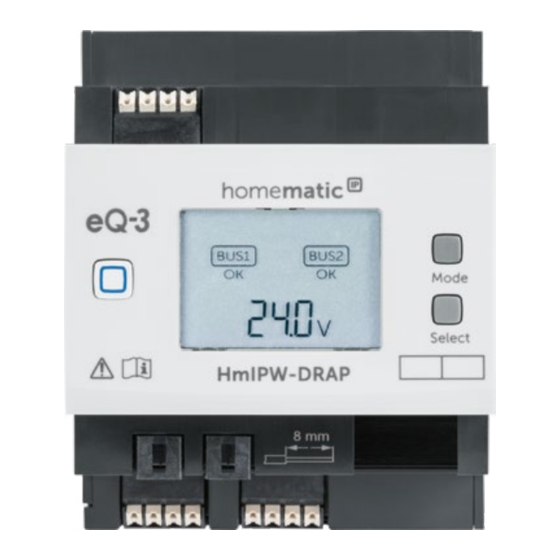
über die Zentrale CCU3 lokal am PC oder per Cloud über die kostenlose Homematic IP App. Der Homematic IP Wired Access Point wird einfach auf ei- ner Hutschiene in der Elektroverteilung installiert. Der An- schluss der Bus-Verbindungskabel erfolgt montagefreund- lich durch vorkonfektionierte Kabel mit Steckverbindern. - Page 13 Funktion und Geräteübersicht Geräteübersicht (s. Abbildung 1): Systemtaste (Anlerntaste und LED) Eingang für die Versorgungsspannung Mode-Taste Select-Taste LC-Display Ethernet-Anschluss Busanschluss 2 Klemmstelle Busanschluss 2 Buchse Busanschluss 1 Buchse Busanschluss 1 Klemmstelle Displayübersicht (s. Abbildung 1): Symbol Bedeutung BUS1 OK BUS2 OK Ringtopologie („Loop“) OK Daten werden vom Bus empfangen Daten werden zum Bus gesendet...
-
Page 14: Allgemeine Systeminformationen
Busklemmen) Stromangabe (Gesamtstrom oder Strom der einzelnen Busse) Allgemeine Systeminformationen Dieses Gerät ist Teil des Homematic IP Smart-Home- Systems und kommuniziert über das Homematic IP Pro- tokoll. Sie haben die Möglichkeit, alle Geräte des Systems komfortabel und individuell über die Bedienoberfläche der Zentrale CCU3 oder flexibel per Smartphone über... -
Page 15: Systemvoraussetzungen
Alternativ können Sie Ihr Wired System flexibel per Smart- phone (mit aktuellem Android- oder iOS-Betriebssystem) über die Homematic IP Cloud in Verbindung mit der Homematic IP App einrichten und steuern. Detaillierte Informationen zu den Systemvoraussetzun- gen und zur Installationsplanung finden Sie im Homema- tic IP Wired Systemhanduch (zu finden im Downloadbe- reich unter www.eQ-3.de). -
Page 16: Topologie Des Bussystems
Topologie des Bussystems Topologie des Bussystems Die Homematic IP Wired Geräte werden für eine störsi- chere und robuste Verbindung untereinander über Buslei- tungen verbunden. Die Topologie des Busses, über den die einzelnen Homematic IP Wired Komponenten verbunden werden, kann beliebig aufgebaut werden. Die folgende Abbildung stellt die möglichen Topologien beispielhaft... -
Page 17: Betriebsarten
Funktionen folgt. Der Homematic IP Wired Bus un- terstützt hierzu den Aufbau einer Ringtopologie („Loop“). Der Bus wird vom Homematic IP Wired Access Point im- mer von einem zum nächsten Gerät und zuletzt wieder zum Homematic IP Wired Access Point geführt, so dass eine Schleife entsteht. -
Page 18: Inbetriebnahme
Beachten Sie die auf dem Gerät angegebene Ab- isolierlänge der anzuschließenden Leiter. Aus Gründen der elektrischen Sicherheit darf zum Anschluss des Homematic IP Wired Bus (I und H) ausschließlich das mitgelieferte Home- matic IP Wired Buskabel oder ein als Zubehör erhältliches eQ-3 Homematic IP Wired Buskabel... - Page 19 Inbetriebnahme Durch eine unsachgemäße Installation gefährden Sie • Ihr eigenes Leben; • das Leben der Nutzer der elektrischen Anlage. Mit einer unsachgemäßen Installation riskieren Sie schwere Sachschäden, z. B. durch Brand. Es droht für Sie die persönliche Haftung bei Personen- und Sachschäden. Wenden Sie sich an einen Elektroinstallateur! Erforderliche Fachkenntnisse für die Installation: Für die Installation sind insbesondere folgende Fachkenntnisse er-...
-
Page 20: Zugelassene Leitungsquerschnitte
Aderendhülse [mm 0,25-1,50 0,25-1,50 Auswahl der Spannungsversorgung Die Spannungsversorgung des Homematic IP Wired Ac- cess Points erfolgt über ein separates Netzteil. Verwen- den Sie für die Spannungsversorgung ein Netzteil, das für den Einsatz in der Gebäudeautomation vorgesehen ist. Die Basisanforderungen für diese Netzteil sind: •... - Page 21 Inbetriebnahme Beachten Sie bei der Auswahl des Netzteils, dass die Zuleitung vom Netzteil zum Wired Access Point maximal 3 m betragen darf. Jeder Busstrang kann maximal 3 A Dauerstrom liefern, sofern das Netzteil entsprechend ausge- legt ist.
-
Page 22: Vorschlag Zur Kabelbelegung Und Farbzuordnung
Inbetriebnahme... -
Page 23: Montage Und Installation
Inbetriebnahme Montage und Installation Bitte lesen Sie diesen Abschnitt erst vollständig, bevor Sie mit der Installation beginnen. Bitte notieren Sie sich vor der Installation die auf dem Gerät angebrachte Gerätenummer (SGTIN) und den Verwendungszweck, damit Sie das Gerät im Nachhinein leichter zuordnen können. Alter- nativ steht die Gerätenummer auch auf dem bei- liegenden QR-Code-Aufkleber. - Page 24 Inbetriebnahme Anschluss (F) und verbinden Sie es mit einem Router. • Schließen Sie ein zuvor installiertes 24 V-Netzteil über den Eingang für die Versorgungsspannung (B) polungsrichtig an den Wired Access Point an. • Schließen Sie das Bus-Verbindungskabel an den Busanschluss 1 (I bzw. J) oder Busanschluss 2 (H bzw.
-
Page 25: Einrichtungs- Und Anlernmöglichkeiten
CCU3 anzulernen und anschließend über die WebUI Bedienoberfläche zu konfigurieren. Alternativ können Sie den Wired Access Point für eine flexible Steuerung per Homematic IP Smartphone- App an die Homematic IP Cloud anlernen. Dabei ist es möglich, das Wired System • per Smartphone-App direkt über den Homema- tic IP Wired Access Point (HmIPW-DRAP) zu steu-... -
Page 26: Anlernen An Die Zentrale Ccu3
Sie wie folgt vor: • Richten Sie zunächst Ihre Zentrale CCU3 gemäß der zugehörigen Bedienungsanleitung ein. • Starten Sie die Benutzeroberfläche „Homematic WebUI“ auf Ihrem PC. • Klicken Sie unter „Einstellungen“ auf „System- steuerung“ im rechten oberen Bereich des Brow- serfensters. -
Page 27: Anlernen An Die Homematic Ip Cloud Per Homematic Ip App
7.6.2 Anlernen an die Homematic IP Cloud per Homematic IP App Wenn Sie Ihre Homematic IP Wired Geräte flexibel per Smartphone-App steuern möchten, können Sie den Wi- red Access Point einfach an die Homematic IP Cloud an- lernen. Gehen Sie dazu wie folgt vor: •... - Page 28 Das Anlernen wird durchgeführt. • Der Wired Access Point ist nun eingerichtet und sofort einsatzbereit. Nachdem der Wired Access Point erfolgreich eingerichtet wurde, können Sie weitere Homematic IP Wired Geräte anlernen. Weitere Informationen dazu entnehmen Sie der Bedienungsanleitung des jeweiligen Geräts.
-
Page 29: Bedienung
Bedienung Wenn Sie bereits Homematic IP Geräte im Smart- Home-System nutzen oder Ihre Wired Geräte mit Funk-Komponenten von Homematic IP kombinie- ren möchten, können Sie die Homematic IP Wired Geräte auch einfach an einen (bestehenden) Homematic IP Access Point anlernen. Lernen Sie dazu den Homematic IP Wired Access Point ge- mäß... - Page 30 Bedienung • Dreimal drücken = Bus 1 und Bus 2 Durch kurzes Drücken der Select-Taste schalten Sie zwi- schen den folgenden Werten: • Für die einzelnen Busstränge werden Spannung und Strom (nur Werte > 100 mA) angezeigt. • Für die einzelnen oder beiden Busstränge werden Eingangsspannung und Gesamtstrom für beide Busse sowie die Temperatur im Gehäuse angezeigt.
-
Page 31: Fehlercodes Und Blinkfolgen
Fehlercodes und Blinkfolgen Fehlercodes und Blinkfolgen Blinkcode/ Bedeutung Lösung LCD-Anzeige Dauerhaft Wired Access Warten Sie kurz oranges Point startet ab und achten Sie Leuchten auf das folgende Blinkverhalten. Schnelles Verbindung Warten Sie bis die blaues zum Server wird Verbindung aufge- Blinken aufgebaut baut wurde und die... - Page 32 Fehlercodes und Blinkfolgen Abwechselnd Update wird Warten Sie, bis das langes und durchgeführt Update abgeschlos- kurzes oran- sen wurde. ges Blinken Schnelles Fehler beim Prüfen Sie die Ser- rotes Update ver- und Internet- Blinken verbindung. Starten Sie den Access Point neu. Schnelles Vorstufe zum Drücken Sie die Sys-...
-
Page 33: Wiederherstellung Der Werkseinstellungen
Wiederherstellung der Werkseinstellungen Die konfigu- Überprüfen Sie rierte und die die Bustopologie tatsächliche oder passen Sie die Bus-Verkabelung Einstellungen an. stimmen nicht Beseitigen Sie ggf überein. Fehler. Kurzschluss der Beheben Sie den Spannungsver- Kurzschluss und sorgung quittieren Sie den Fehler (s. „8 Be- dienung“... -
Page 34: Wartung Und Reinigung
Wartung und Reinigung • Lassen Sie die Systemtaste wieder los, um das Wiederherstellen der Werkseinstellungen abzu- schließen. Das Gerät führt einen Neustart durch. Nach dem Neustart können Sie das Gerät wieder ins System integrieren. Wartung und Reinigung Das Gerät ist wartungsfrei. Überlassen Sie eine Wartung oder Reparatur einer Fachkraft. -
Page 35: Technische Daten
Stromaufnahme im Ruhebetrieb ohne angeschlossene Geräte: 55 mA Leistungsaufnahme Ruhebetrieb: 1320 mW Busausgänge 2x Homematic IP Wired Bus (24 V ; max. 3 A pro Busausgang, RS485 Bus) Länge HmIPW Bus: 300 m max. Anzahl Geräte pro Bus: 64 max. - Page 36 Technische Daten Technische Änderungen vorbehalten. Entsorgungshinweis Gerät nicht im Hausmüll entsorgen! Elektroni- sche Geräte sind entsprechend der Richtlinie über Elektro- und Elektronik-Altgeräte über die örtlichen Sammelstellen für Elektronik-Altgeräte zu entsorgen. Konformitätshinweis Das CE-Zeichen ist ein Freiverkehrszeichen, das sich ausschließlich an die Behörden wendet und keine Zusicherung von Eigenschaften beinhaltet.
- Page 37 Package contents Quantity Description Homematic IP Wired Access Point Bus connection cable Bus blind plug Network cable User manual Documentation © 2018 eQ-3 AG, Germany. All rights reserved. Translation from the original version in Ger- man. This manual may not be reproduced in any format, either in...
- Page 38 Set-up and teach-in options ..........55 7.6.1 Connecting to the Homematic IP Central Control Unit CCU3 ..........56 7.6.2 Teaching-in to the Homematic IP cloud via Homematic IP app ..........58 Operation .................59 Error codes and flashing sequences ......61 10 Restore factory settings ..........63 Maintenance and cleaning ..........
-
Page 39: Information About This Manual
Information about this manual Information about this manual Please read this manual carefully before beginning op- eration with your Homematic IP Wired component. Keep the manual so you can refer to it at a later date if you need to. - Page 40 Hazard information Do not use the device if there are signs of dam- age to the housing, control elements or connect- ing sockets, for example. If you have any doubts, have the device checked by an expert. The device may only be operated in dry and dust- free environment and must be protected from the effects of moisture, vibrations, solar or other methods of heat radiation, cold and mechanical...
- Page 41 Homematic IP Wired bus only. The Homematic IP Wired bus is a SELV power circuit. The power supply of the building installation and the Homematic IP Wired bus have to be laid separately. Common cable routing for power supply and the Homematic IP Wired bus in installation and junction boxes is not permitted.
- Page 42 Hazard information For secure operation, the device has to be installed in a power distribution panel according to VDE 0603, DIN 43871 (low-voltage sub-distribution board), DIN 18015-x. The installation must be carried out on a mounting rail (DIN rail) according to EN 60715.
-
Page 43: Function And Device Overview
Function and device overview Function and device overview The Homematic IP Wired Access Point is the central inter- face of the Homematic IP Wired system and offers supply voltage for the entire bus in combination with a power supply unit. The device is simply connected via Ethernet... - Page 44 Function and device overview Device overview (see figure 1): System button (teach-in/pairing button and LED) Input for supply voltage Mode button Select button LC display Ethernet connection Bus terminator 2 clamp terminal Bus terminator 2 socket Bus terminator 1 socket Bus terminator 1 clamp terminal Display overview (see figure 1): Symbol...
-
Page 45: General System Information
Current indication (total current or current of single bus) General system information This device is part of the Homematic IP smart home system and works with the Homematic IP protocol. All devices of the system can be configured comfortably and individually with the user interface of the Central Control Unit CCU3 or flexibly via the Homematic ... -
Page 46: System Requirements
System requirements System requirements The Homematic IP Wired system uses the bus data line for internal communication between the wired devices. While the bus connecting cables for wiring within the control cabinet are already included in the package con- tent, a four-wire bus line is required for communication of external devices. -
Page 47: Topology Of The Bus System
For interfence-proof and robust connection, the Home- matic IP Wired devices are connected via bus lines. The topology of the bus that connects the single Homematic IP Wired components can be established as required. The following figure shows possible topologies as example (no connecting diagram). -
Page 48: Operating Modes
Operating modes 6.2.1 Ring topology For the first time, Homematic IP Wired offers easy instal- lation of fault-tolerant networks for a house or building bus system. Even in case of interruptions of the lines, there will be no device or function failures. The Home- matic ... -
Page 49: Start-Up
For electrical safety reasons, only the supplied Homematic IP Wired Bus Cable may be used for connecting the device to the Homematic IP Wired bus (I and H). Furthermore, an eQ-3 Homematic IP Wired Bus Cable with other lengths (available as accessory) can be used. - Page 50 Start-up Please note! Only to be installed by persons with the relevant electro-technical knowledge and experience!* Incorrect installation can put • your own life at risk; • and the lives of other users of the electrical system. Incorrect installation also means that you are running the risk of serious damage to property, e.g.
-
Page 51: Permissible Cable Cross Sections
0.25-1.50 0.25-1.50 Selecting the supply voltage Voltage is supplied to the Homematic IP Wired Access Point via a separate power supply unit. Please use a pow- er supply unit that is appropriate for application in house installations. The basic requirements to the power supply unit are: •... - Page 52 Start-up When selecting the power supply unit, please note that the supply cable from the network to the Wired Access Point may not exceed 3 m. Every bus line can supply 3 A continuous current max., as far as the power supply unit is able to provide it.
-
Page 53: Recommendation For Cable Occupation And Colour Allocation
Start-up... -
Page 54: Mounting And Installation
Start-up Mounting and installation Please read this entire section before starting to install the device. Before installation, please note the device num- ber (SGTIN) labelled on the device as well as the exact application purpose in order to make later allocation easier. -
Page 55: Set-Up And Teach-In Options
Please read this entire section before starting the teach-in procedure. You will find further details and overviews about the set-up options in the Homematic IP Wired Installation Guide. In this way, you can teach-in the Wired Access Point to the Central Control Unit CCU3 for local configuration via... -
Page 56: Connecting To The Homematic Ip Central Control Unit Ccu3
Start-up As an alternative, connect the Wired Access Point to the Homematic IP cloud for flexible control via Homematic IP smartphone app. You can • control the wired system directly via smartphone app using the Homematic IP Wired Access Point (HmIPW-DRAP) or •... - Page 57 In the next window, click on “Homematic IP Access Point”. • Follow the instructions in the user interface. Detailed information about setting up the Wired Access Point can be found in the Homematic IP Wired System Manual (available in the download area of www.eQ-3.com).
-
Page 58: Teaching-In To The Homematic Ip Cloud Via Homematic Ip App
7.6.2 Teaching-in to the Homematic IP cloud via Homematic IP app If you want to control your Homematic IP Wired devices flexibly via smartphone app, you can simply connect the Wired Access Point to the Homematic IP cloud. To do this, please proceed as follows: •... -
Page 59: Operation
For further information, please refer to the oper- ating manual of the corresponding device. If you are already using Homematic IP devices in your smart home system or if you want to com- bine your Homematic IP Wired devices with wire-... - Page 60 Operation the LCD background lighting of all devices connected to the bus. Display values You can select between the single or both bus lines by pressing the mode button briefly: • Pressing once = bus 1 • Pressing twice = bus 2 •...
-
Page 61: Error Codes And Flashing Sequences
Error codes and flashing sequences see „9 Error codes and flashing sequences“ on page 61), the error must be acknowledged by the user. Press and hold down the select button to change to the error acknowledgement. You can switch between the errors by pressing the select button briefly. - Page 62 Error codes and flashing sequences Permanent Router function You can continue turquoise active (when operation. lighting operating with several Access Points) Fast yellow No connection Connect the Ac- flashing to network or cess Point to the router network/router. Permanent No Internet con- Please check the yellow light- nection...
-
Page 63: Restore Factory Settings
Restore factory settings Temperature too Reduce the con- high nected load and let the device cool down. Short circuit Remove the short between data circuit. line and 24 V The configured Please check the and actual bus bus topology and cabling does not adjust the settings. -
Page 64: Maintenance And Cleaning
Maintenance and cleaning • Press and hold down the system button again for 4 seconds, until the LED lights up green. • Release the system button to finish the proce- dure. The device will perform a restart. After the restart, you can again integrate your device into the system. -
Page 65: Technical Specifications
55 mA Power consumption in standby: 1320 mW Bus outputs: 2x Homematic IP Wired Bus (24 V ; max. 3 A per bus output, RS485 Bus) HmIPW bus length: 300 m max. Number of devices per bus: 64 max. - Page 66 Subject to technical changes. Instructions for disposal Do not dispose of the device with regular domes- tic waste! Electronic equipment must be dis- posed of at local collection points for waste elec- tronic equipment in compliance with the Waste Electrical and Electronic Equipment Directive. Information about conformity The CE sign is a free trading sign addressed ex- clusively to the authorities and does not include...
- Page 67 Kostenloser Download der Homematic IP App! Free download of the Homematic IP app! Bevollmächtigter des Herstellers: Manufacturer’s authorised representative: eQ-3 AG Maiburger Straße 29 26789 Leer / GERMANY www.eQ-3.de...
Need help?
Do you have a question about the HmIPW-DRAP and is the answer not in the manual?
Questions and answers