Table of Contents
Advertisement
Quick Links
Advertisement
Table of Contents

Related Manuals for Supermicro SYS-621BT-DNC8R


Summary of Contents for Supermicro SYS-621BT-DNC8R
- Page 1 WEEE DISASSEMBLY INSTRUCTIONS SUPERMICRO SYS-621BT-DNC8R ENCLOSURE Abstract This document provides clear guidance for end-of-life recyclers on how to identify and disassemble reportable materials in compliance with the Waste Electrical and Electronic Equipment (WEEE) directive.
-
Page 2: Table Of Contents
Table of Contents Product Views ............................1 Reportable Materials on SYS-621BT-DNC8R ..................... 3 Disassemble Instructions .......................... 4 3.3 Step-by-Step Disassembly Instructions ....................7 Removing Cable and Chassis Top Cover ................... 7 Removing Hard Disk Drive ........................ 8 Removing Power Supply ........................9 Removing Power Distributor...................... -
Page 3: Product Views
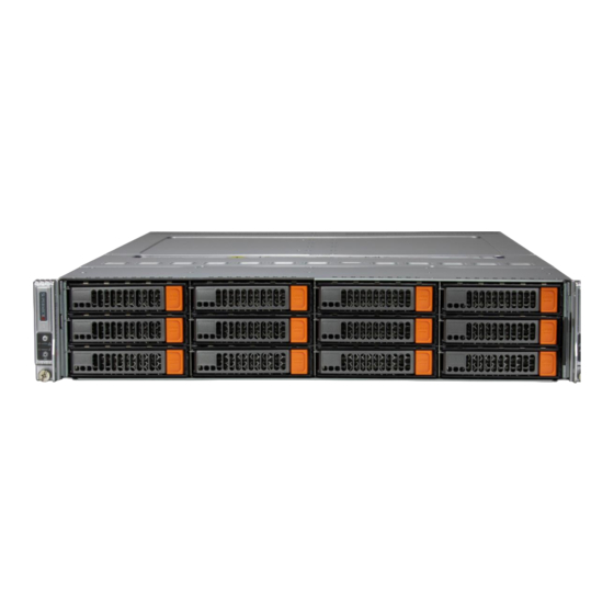
1. Product Views Front view Rear view Product construct view Hard Disk Drive/ Solid State Drive Backplane... - Page 4 Node B Node A Power Supply Node construct view...
-
Page 5: Reportable Materials On Sys-621Bt-Dnc8R
2. Reportable Materials on SYS-621BT-DNC8R According to Article 8(2) and Annex VII of WEEE directive 2012/19/EU, Below materials and components should be selectively treated. Description Notes Quantity With a surface greater than 10 sq cm Printed Circuit Boards (PCB) or 2.4, 3.5, 4.2, 5.1, 7.2, 8.2,... -
Page 6: Disassemble Instructions
Components, parts, and materials containing radioactive substances 3. Disassemble Instructions The intent of this document is to provide guidance to recyclers on the presence of materials and components at the product / family level, as required by the EU WEEE Directive 2012/10/EU. This document should also help direct recyclers to proper methods for removing parts and general product disassembly instructions. - Page 7 Chassis Chassis Enclosure Fan Holder Sponge Screw, Stand-off Motherboard Storage Controller Card Storage Controller Card Riser Card Storage Controller Card Cable Battery...
- Page 8 Power Supply Power Enclosure Screw and Standoff Power Supply Module Power Cable Storage Card and CPU Heat Sink Processor Solid State Drive AIOM Card DIMM...
-
Page 9: Step-By-Step Disassembly Instructions
3.3 Step-by-Step Disassembly Instructions Note: Depending on product configuration, it will be different 1. Removing Cable and Chassis Top Cover 1. Use the operating system to power down the system. 2. After the system has completely shut-down, disconnect the power cords from the power supply modules. -
Page 10: Removing Hard Disk Drive
2. Removing Hard Disk Drive 1. Push the release button on the drive carrier, which will extend the drive bay handle 2. Use the drive bay handle to pull the drive carrier out of the chassis 3. Remove the dummy tray insert by first removing two screws, then pull out the dummy tray 5. -
Page 11: Removing Power Supply
6. Use a cross screwdriver to remove the screws and lift off the PCB Description Dummy Tray Hard Drive Hard Drive Enclosure Hard Drive PCB 3. Removing Power Supply 1. Press the release tab on the failed power supply. 2. Use the handle to gently slide the power supply out the back of the chassis. 3. -
Page 12: Removing Power Distributor
4. Cut the power leads connected to the fan and lift the main board from the chassis Description Power Supply Power Enclosure Fan Cable Power Module PCB Capacitor 4. Removing Power Distributor 1. Disconnect the power cords from the power supply modules. Remove screws and lift out the power distributor from the chassis... -
Page 13: Removing Backplane
Description Power Distributor Power Distributor PCB 5. Removing Backplane 1. Remove the backplane 8 screws from the chassis Description Backplane 6. Removing Fan 1. Disconnect the chassis fan to the motherboard Fan1-Fan4 connector Description Cooling Fan... -
Page 14: Removing Aiom Card
7. Removing AIOM Card Press the node holder, then hold the node and pull the node from the chassis Press the release tab and loosen the thumbscrew on the AIOM card Grasp the release tab and the thumbscrew and pull the AIOM out of the node tray Description Node AIOM Card... -
Page 15: Removing Processor
9. Removing Processor 1. Removing the PHM (Processor Heatsink Module ) from the motherboard, first shut down the system and unplug the AC power cord from all power supplies. 2. Use a T30-bit screwdriver to loosen the four peek nuts on the heatsink in the sequence of A, B, C, and D. 3. - Page 16 6. When all plastic clips have been detached from the heatsink, remove the processor carrier assembly from the heatsink. 7. Unlock the lever from its locked position and push it upwards to disengage the processor from the processor carrier, as shown below on the right. 8.
-
Page 17: Removing Dimm
10. Removing DIMM 10.1 1. Use your hand press both release tabs on the ends of the DIMM module to unlock it. 2. Once the DIMM module is loose, remove it from the memory slot. Description 10.1 DIMM 11. Removing M.2 Remove each screw from the bracket Take the M.2 card and bracket away from the chassis 11.1... - Page 18 12.2 12.1 Description 12.1 Motherboard 12.2 Battery Note: Repeat steps 1-12 of each node disassembled, then the chassis enclosure can be recycled.
Need help?
Do you have a question about the SYS-621BT-DNC8R and is the answer not in the manual?
Questions and answers