
Subscribe to Our Youtube Channel
Related Manuals for Keithley KUSB-3160


Summary of Contents for Keithley KUSB-3160
- Page 1 KUSB-3160 User’s Manual KUSB3160-900-01 Rev. A / January 2005 G R E A T E R M E A S U R E C O N F I D E N C E...
- Page 2 WARRANTY Keithley Instruments, Inc. warrants this product to be free from defects in material and workmanship for a period of 3 years from date of shipment. Keithley Instruments, Inc. warrants the following items for 90 days from the date of shipment: probes, cables, rechargeable batteries, diskettes, and documentation.
- Page 3 KUSB-3160 User’s Manual ©2005, Keithley Instruments, Inc. All rights reserved. First Printing, January 2005 Cleveland, Ohio, U.S.A. Document Number: KUSB3160-900-01A Rev. A...
- Page 4 Revision of the manual. Each new Revision includes a revised copy of this print history page. Revision A (Document Number KUSB3160-900-01A)..............January 2005 All Keithley product names are trademarks or registered trademarks of Keithley Instruments, Inc. Other brand and product names are trademarks or registered trademarks of their respective holders.
- Page 5 Keithley products are designed for use with electrical signals that The instrument and accessories must be used in accordance with its are rated Measurement Category I and Measurement Category II, as...
- Page 6 Keithley Instru- symbol on an instrument indicates that the user should re- ments. Standard fuses, with applicable national safety approvals, fer to the operating instructions located in the manual.
-
Page 7: Table Of Contents
Table of Contents About this Manual ........Intended Audience. - Page 8 Contents Appendix A: Specifications ......Appendix B: Connector Pin Assignments ... . . Index .
-
Page 9: About This Manual
About this Manual This manual describes the features of the KUSB-3160 module, the capabilities of the device driver, and how to program the KUSB-3160 module using DT-Open Layers™ software. Troubleshooting information is also provided. Intended Audience This document is intended for engineers, scientists, technicians, or others responsible for using and/or programming the KUSB-3160 module for data acquisition operations in the Microsoft®... -
Page 10: Conventions Used In This Manual
Refer to the following documents for more information on using the KUSB-3160 module: • KUSB-3160 Getting Started Manual. This manual describes the how to install the KUSB-3160 module and related software. • DataAcq SDK User’s Manual. For programmers who are... -
Page 11: Where To Get Help
• Microsoft Windows 2000 or Windows XP documentation. • USB web site (http://www.usb.org). Where To Get Help Should you run into problems installing or using your KUSB-3160 module, please call the Keithley Technical Support Department. - Page 12 About this Manual...
-
Page 13: Chapter 1: Overview
Overview Key Features ..........Supported Software . -
Page 14: Key Features
Chapter 1 Key Features The KUSB-3160 is a low-cost, high-power, digital I/O module for the Universal Serial Bus (USB). The KUSB-3160 module provides the following major features: • USB compatibility; • 64 configurable digital I/O lines (configurable in banks of eight) and 32 dedicated digital input lines for nonclocked monitoring or control. -
Page 15: Supported Software
• Quick Data Acq application − This application provides a quick way to get a KUSB-3160 module up and running. Using the Quick Data Acq application, you can verify the features of the module, display data on the screen, and save data to disk. -
Page 16: Accessories
KUSB-3160 module using the KUSB-CABDIO cable. This screw terminal panel allows you to connect all of the input and output connections that are supported by a KUSB-3160 module. LEDs on up to 64 of the outputs light when the outputs are low. - Page 17 Principles of Operation Digital I/O Lines ........Resolution .
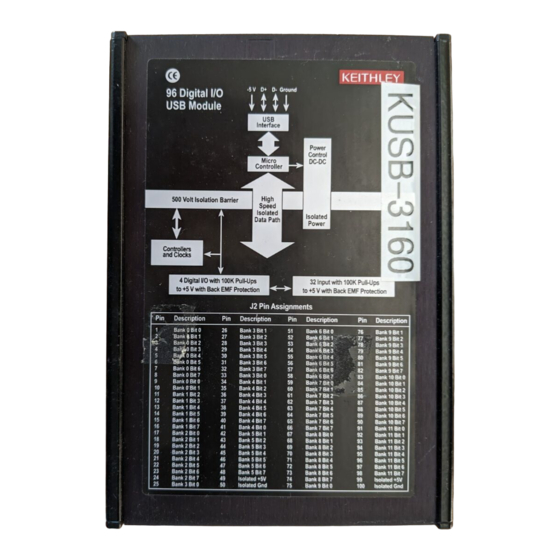
- Page 18 Chapter 2 Figure 1 shows a block diagram of the KUSB-3160 module. Note that bold entries indicate signals you can access. Pins 1 to 64 Lines 0 to 63 Pins 50 and 100 64 Digital I/O WIth 100 kΩ Pull-Ups to +5V_I...
-
Page 19: Chapter 2: Principles Of Operation
Principles of Operation This chapter describes the following features of the digital I/O subsystem: • Digital I/O lines, described on page • Resolution, described on page • Interrupts, described on page 13, and • Operation modes, described on page... -
Page 20: Digital I/O Lines
When debounce is not selected (the default configuration), a delay of less than 1 ms occurs. Refer to the KUSB-3160 Getting Started Manual for more information. Outputs are open collectors with a 100 kΩ resistor connected to the internal isolated +5 V. - Page 21 Principles of Operation You can specify the digital input lines to read in a single-value digital I/O or continuous operation. You can specify the digital output lines to write to in a single-value digital I/O operation. Refer to page 14 more information on digital I/O operation modes.
-
Page 22: Resolution
Chapter 2 Resolution Using software, specify the number of digital I/O lines to read or write at once by specifying the resolution as 8, 16, 24, or 32. Table 1 shows the effect of resolution on the number of DIN and DOUT subsystems available for a bank. - Page 23 Principles of Operation Table 1: Resolution, Digital I/O Lines, and Number of Subsystems (cont.) DIN or DOUT Resolution Digital I/O Lines Subsystem Banks 0 and 1, lines 0 Element 0 and 15 combined Banks 2 and 3, lines 0 Element 2 and 15 combined Banks 4 and 5, lines 0 Element 4...
- Page 24 Chapter 2 For example, if you specify a resolution of 8, you can read or write to each digital bank separately by specifying element number 0 to 11. If you specify a resolution of 16, you can read or write to two banks at once by specifying element 0, 2, 4, 6, 8, or 10.
-
Page 25: Interrupts
Principles of Operation Interrupts The KUSB-3160 module can generate a PCI-bus interrupt when any of the digital input lines corresponding to banks 10 and 11 changes state. This feature is useful when you want to monitor critical signals or when you want to signal the host computer to transfer data to or from the module. -
Page 26: Operation Modes
Chapter 2 Operation Modes KUSB-3160 modules support the following digital I/O operation modes: • Single-value operations are the simplest to use but do not allow you to check the interrupt status. Use software to specify the DIN or DOUT subsystem, the resolution, and a gain of 1 (the gain is ignored). -
Page 27: Chapter 4: Programming Flowcharts
Programming Flowcharts Single-Value Operations ....... . . Continuous Digital Input Operations ..... . - Page 28 Chapter 4 The following flowcharts show the steps required to perform data acquisition operations using DT-Open Layers. For illustration purposes, the DataAcq SDK functions are shown; however, the concepts apply to all DT-Open Layers software. Note that many steps represent several substeps; if you are unfamiliar with the detailed operations involved with any one step, refer to the indicated page for detailed information.
-
Page 29: Single-Value Operations
Programming Flowcharts Single-Value Operations Initialize the device driver and get the device handle with olDaInitialize. Specify DIN for a digital input subsystem or Get a handle to the subsystem with DOUT for a digital output subsystem. olDaGetDASS. Set the data flow to OL_DF_SINGLEVALUE using olDaSetDataFlow. - Page 30 Chapter 4 Continued from previous page. Acquire a single value using Acquiring olDaGetSingleValue. data? Acquire/ Output a single value using output olDaPutSingleValue. another value? Release the subsystem using olDaReleaseDASS. Release the driver and terminate the session using olDaTerminate.
-
Page 31: Continuous Digital Input Operations
Programming Flowcharts Continuous Digital Input Operations Initialize the device driver and get the device handle with olDaInitialize. Get a handle to the DIN subsystem with Only banks 10 and 11 support continuous digital input operations. olDaGetDASS. Set the data flow to OL_DF_CONTINUOUS using olDaSetDataFlow. - Page 32 Chapter 4 Continued from previous page. Configure the subsystem using olDaConfig. Start the operation with olDaStart. The event done message is OLDA_WM_EVENT_DONE. In olDaSetWndHandle or olDaSetNotificationProcedure, the subsystem handle, HDASS, is returned in the wParam parameter; this allows one window to handle messages from both subsystems.
- Page 33 Programming Flowcharts Stop the Operation Stop in an olDaStop stops the operation on the subsystem in an orderly way. orderly olDaStop way? olDaAbort and olDaReset stop the Reinitialize? olDaReset operation on the subsystem immediately. olDaReset also reinitializes the subsystem to a known state.
- Page 34 Chapter 4 Clean up the Operation Release each subsystem. olDaReleaseDASS Release the device driver and terminate the olDaTerminate session.
- Page 35 Supported Device Driver Capabilities...
- Page 36 Chapter 3 The KUSB-3160 Device Driver provides support for DIN and DOUT subsystems. For information on how to configure the device driver, refer to the KUSB-3160 Getting Started Manual. Table 2 summarizes the features available for use with the DataAcq SDK and the KUSB-3160 modules.
- Page 37 Supported Device Driver Capabilities Table 2: KUSB-3160 Supported Options KUSB-3160 DOUT SRL C/T Total Subsystems on Board Single-Value Operation Support OLSSC_SUP_SINGLEVALUE Continuous Operation Support OLSSC_SUP_CONTINUOUS Continuous Operation until Trigger Event Support OLSSC_SUP_CONTINUOUS_PRETRIG Continuous Operation before and after Trigger Event OLSSC_SUP_CONTINUOUS_...
- Page 38 Chapter 3 Table 2: KUSB-3160 Supported Options (cont.) KUSB-3160 DOUT SRL C/T Total Subsystems on Board Number of DMA Channels OLSSC_NUMDMACHANS Supports Gap Free Data with No DMA OLSSC_SUP_GAPFREE_NODMA Supports Gap Free Data with Single DMA OLSSC_SUP_GAPFREE_SINGLEDMA Supports Gap Free Data with Dual DMA...
- Page 39 Supported Device Driver Capabilities Table 2: KUSB-3160 Supported Options (cont.) KUSB-3160 DOUT SRL C/T Total Subsystems on Board Simultaneous Sample and Hold Support OLSSC_SUP_SIMULTANEOUS_SH Random Channel-Gain List Support OLSSC_SUP_RANDOM_CGL Channel List Inhibit Support OLSSC_SUP_CHANNELLIST_ INHIBIT Programmable Gain Support OLSSC_SUP_PROGRAMGAIN Number of Gains...
- Page 40 Chapter 3 Table 2: KUSB-3160 Supported Options (cont.) KUSB-3160 DOUT SRL C/T Total Subsystems on Board Filter/Channel Support OLSSC_SUP_FILTERPERCHAN Number of Filters OLSSC_NUMFILTERS Number of Voltage Ranges OLSSC_NUMRANGES Range per Channel Support OLSSC_SUP_RANGEPERCHANNEL Software Programmable Resolution OLSSC_SUP_SWRESOLUTION Number of Resolutions...
- Page 41 Supported Device Driver Capabilities Table 2: KUSB-3160 Supported Options (cont.) KUSB-3160 DOUT SRL C/T Total Subsystems on Board Internal Clock Support OLSSC_SUP_INTCLOCK External Clock Support OLSSC_SUP_EXTCLOCK Number of Extra Clocks OLSSC_NUMEXTRACLOCKS Base Clock Frequency OLSSCE_BASECLOCK Maximum External Clock Divider OLSSCE_MAXCLOCKDIVIDER...
- Page 42 Chapter 3 Table 2: KUSB-3160 Supported Options (cont.) KUSB-3160 DOUT SRL C/T Total Subsystems on Board High to Low Output Pulse Support OLSSC_SUP_PLS_HIGH2LOW Low to High Output Pulse Support OLSSC_SUP_PLS_LOW2HIGH None (internal) Gate Type Support OLSSC_SUP_GATE_NONE High Level Gate Type Support...
- Page 43 Digital banks 10 and 11 can generate an interrupt on a bit-by-bit basis. You configure the digital lines to interrupt using the Open Layers Control Panel. Refer to the KUSB-3160 Getting Started Manual for more information.
- Page 44 Chapter 3...
-
Page 45: Chapter 5: Troubleshooting
Troubleshooting General Checklist ........Service and Support . -
Page 46: General Checklist
“Read This First” information to your manual and that you have used this information. Check the Keithley CD for any README files and ensure that you have used the latest installation and configuration information available. - Page 47 Intermittent Loose connections or Check your wiring and tighten any loose operation. vibrations exist. connections or cushion vibration sources; see the instructions in the KUSB-3160 Getting Started Manual. The module is Check environmental and ambient overheating. temperature; consult the module’s...
- Page 48 KUSB-3160 Getting Started Manual. A signal source is not Check the transducer connections; see connected to the the instructions in the KUSB-3160 Getting channel being read. Started Manual. Computer does The power supply of Check the power requirements of your not boot.
-
Page 49: Service And Support
For the latest tips, software fixes, and other product information, you can always access our World-Wide Web site at the following address: http://www.keithley.com If you have difficulty using a KUSB-3160 module, the Keithley Technical Support Department is available to provide technical assistance. - Page 50 Chapter 5 Information Required for Technical Support Name:___________________________________________Phone__________________________ Contract Number: __________________________________________________________________ Address: _________________________________________________________________________ ________________________________________________________________________________ Hardware product(s): _______________________________________________________________ serial number: _________________________________________________________________ configuration: _________________________________________________________________ Device driver: ____________________________________ ________________________________ _______________________________________________ version: _________________________ Software: ________________________________________ ________________________________ serial number: ________________________________ version:__________________________ PC make/model: ___________________________________________________________________ operating system: _____________________________ version:__________________________ Windows version: ______________________________________________________________ processor: ___________________________________ speed:___________________________ RAM: _______________________________________ hard disk space: ____________________...
- Page 51 Specifications...
- Page 52 Low-level input current: Back EMF diodes a. The KUSB-3160 module can generate a PCI-bus interrupt when any of the digital input lines corresponding to banks 10 and 11 changes state. b. You can drive the +5V_I isolated output pin from an external power supply. This will allow the last digital output value to be latched to the input stage;...
- Page 53 Current requirements are 50 mA plus load. Table 7 lists the power, physical, and environmental specifications for the KUSB-3160 module. Table 7: Power, Physical, and Environmental Specifications Feature Specifications Power µ...
- Page 54 Appendix A Table 8 lists the cable and connector specifications for the KUSB-3160 module. Table 8: KUSB-3160 Cable and Connector Specifications Feature Specifications USB cable 2-meter, Type A-B, USB cable AMP part# 974327-1 J1 Connector 100-pin D, Robinson Nugent part# P50E-100P1-SR1-TG...
- Page 55 Connector Pin Assignments...
- Page 56 Appendix B Table 9 lists the pin assignments of connector J1 on the KUSB-3160 module and on the KUSB-STP100 screw terminal panel. Note: Because of different vendor number pinning schemes, the Robinson Nugent connector specified on page 42 has a mirror pinout from that described in this appendix.
- Page 57 Connector Pin Assignments Table 9: Pin Assignments for Connector J1 (cont.) Number Signal Description Number Signal Description Bank 3, Bit 2 Bank 3, Bit 3 Bank 3, Bit 4 Bank 3, Bit 5 Bank 3, Bit 6 Bank 3, Bit 7 Bank 4, Bit 0 Bank 4, Bit 1 Bank 4, Bit 2...
- Page 58 Bank 11, Bit 6 Bank 11, Bit 7 Isolated +5 V Isolated Ground a. Dedicated digital input line. The KUSB-3160 module can generate a PCI-bus interrupt when any of the digital input lines (bits) corresponding to banks 10 and 11 changes state.
- Page 59 Connector Pin Assignments Table 10 lists the screw terminal assignments of the KUSB-STP100 screw terminal panel. Table 10: Screw Terminal Assignments of the KUSB-STP100 Screw Terminal Panel Screw Terminal Terminal Block Number Signal Description Bank 0, Bit 0 Bank 0, Bit 1 Bank 0, Bit 2 Bank 0, Bit 3 Bank 0, Bit 4...
- Page 60 Appendix B Table 10: Screw Terminal Assignments of the KUSB-STP100 Screw Terminal Panel (cont.) Screw Terminal Terminal Block Number Signal Description TB2 (cont.) Bank 7, Bit 1 Bank 1, Bit 2 Bank 1, Bit 3 Bank 1, Bit 4 Bank 1, Bit 5 Bank 1, Bit 6 Bank 1, Bit 7 Bank 2, Bit 0...
- Page 61 Connector Pin Assignments Table 10: Screw Terminal Assignments of the KUSB-STP100 Screw Terminal Panel (cont.) Screw Terminal Terminal Block Number Signal Description Bank 2, Bit 4 Bank 2, Bit 5 Bank 2, Bit 6 Bank 2, Bit 7 Bank 3, Bit 0 Bank 3, Bit 1 Bank 3, Bit 2 Bank 3, Bit 3...
- Page 62 Appendix B Table 10: Screw Terminal Assignments of the KUSB-STP100 Screw Terminal Panel (cont.) Screw Terminal Terminal Block Number Signal Description Bank 3, Bit 6 Bank 3, Bit 7 Bank 4, Bit 0 Bank 4, Bit 1 Bank 4, Bit 2 Bank 4, Bit 3 Bank 4, Bit 4 Bank 4, Bit 5...
- Page 63 Connector Pin Assignments Table 10: Screw Terminal Assignments of the KUSB-STP100 Screw Terminal Panel (cont.) Screw Terminal Terminal Block Number Signal Description Bank 5, Bit 0 Bank 5, Bit 1 Bank 5, Bit 2 Bank 5, Bit 3 Bank 5, Bit 4 Bank 5, Bit 5 Bank 5, Bit 6 Bank 5, Bit 7...
- Page 64 Appendix B...
-
Page 65: Index
Index Symbols digital I/O features interrupts +5 V power lines operation modes resolution specifications accessories digital input operations DIN subsystem specifications DOUT subsystem specifications banks DT-LV Link base clock frequency DTx-EZ binary data encoding environmental specifications cables external +5 V power KUSB-CABDIO external clock divider channels... - Page 66 Index I/O channels OLDA_WM_EVENT_DONE interrupts olDaAbort IParam olDaConfig in continuous digital input operations in single-value operations J1 connector pin assignments olDaGetDASS in continuous digital input operations in single-value operations KUSB-CABDIO cable olDaGetSingleValue KUSB-STP100 screw terminal panel olDaGetSSCaps olDaGetSSCapsEx olDaInitialize in continuous digital input lines operations in single-value operations...
- Page 67 Index olDaTerminate pin assignments in continuous digital input power specifications operations power, +5 V in single-value operations OLSSC_MAX_DIGITALIOLIST_ VALUE Quick Data Acq application OLSSC_MAXDICHANS OLSSC_MAXSECHANS OLSSC_NUMCHANNELS OLSSC_NUMDMACHANS resolution OLSSC_NUMEXTRACLOCKS retrigger frequency OLSSC_NUMEXTRATRIGGERS OLSSC_NUMFILTERS OLSSC_NUMGAINS OLSSC_NUMRANGES screw terminal assignments OLSSC_NUMRESOLUTIONS screw terminal panel OLSSC_SUP_BINARY service and support procedure OLSSC_SUP_CONTINUOUS...
- Page 68 Index troubleshooting procedure service and support procedure troubleshooting table voltage ranges Windows messages...
- Page 69 M E A S U R E C O N F I D E N C E Keithley Instruments, Inc. Corporate Headquarters • 28775 Aurora Road • Cleveland, Ohio 44139 • 440-248-0400 • Fax: 440-248-6168 • 1-888-KEITHLEY (534-8453) • www.keithley.com 12/04...
Need help?
Do you have a question about the KUSB-3160 and is the answer not in the manual?
Questions and answers