Table of Contents
Advertisement
Quick Links
FOR GAS/DIESEL/GASOLINE GENERATORS
EMKO ELEKTRON K A. .
Ý
Demirta Org. San. Bolg.
þ
Karanfil Sk. No: 6 TR
16369 Bursa / TURKEY
Phone
: +90 224 261 1900
Faks
: +90 224 261 1912
Url
:
www.emkoelektronik.com.tr
E-mail
:
emko@emkoelektronik.com.tr
exposales@emkoelektronik.com.tr
TRANS-MINIAUTO
AUTOMATIC START UNIT
WITH J1939 ECUs
User Manual
Þ
Introduction Manual. ENG TRANS-MINIAUTO 02 V13 03/18
Advertisement
Table of Contents

Related Manuals for EMKO TRANS MINI AUTO


Summary of Contents for EMKO TRANS MINI AUTO
- Page 1 TRANS-MINIAUTO AUTOMATIC START UNIT FOR GAS/DIESEL/GASOLINE GENERATORS WITH J1939 ECUs User Manual EMKO ELEKTRON K A. . Ý Þ Demirta Org. San. Bolg. þ Karanfil Sk. No: 6 TR 16369 Bursa / TURKEY Phone : +90 224 261 1900 Faks : +90 224 261 1912 www.emkoelektronik.com.tr...
-
Page 2: Table Of Contents
CONTENTS 1.Introduction............................Page 1.1 General Specifications......................Page 1.2 Warranty............................ Page 1.3 Maintenance ..........................Page 1.4 Order Information........................Page 2.Installation............................Page 2.1 Unit Configuration........................Page 2.2 Panel Mounting.......................... Page Figure 2.1 Front View........................ Page Figure 2.2 Panel Cut-Out......................Page 2.3 Electrical Connection......................... Page 3.Definition Of Front Panel And Accessing To The Parameters............ - Page 3 EU DECLARATION OF CONFORMITY Manufacturer’s Name : EMKO ELEKTRONIK A.S. Manufacturer’s Address : DOSAB, Karanfil Sk., No:6, 16369 Bursa, TURKEY The manufacturer hereby declares that the product: Product Name Automatic Start Unit Type Number : TRANS-MINIAUTO Product Category : Electrical equipment for measurement, control and...
-
Page 4: Introduction
The configurable inputs can be programmed to perform 28 different functions. 1.2 Warranty EMKO Elektronik warrants that the equipment delivered is free from defects in material and workmanship. This warranty is provided for a period of two years. The warranty period starts from the delivery date. -
Page 5: Installation
2.Installation Ýçindekiler Before beginning installation of this product, please read the instruction manual and warnings below carefully. A visual inspection of this product for possible damage occured during shipment is recommended before installation. It is your responsibility to ensure that qualified mechanical and electrical technicians install this product. - Page 6 2.3 Electrical Connection TRANS-MINIAUTO three phase connections schematic BATTERY - FUSE-2 BATTERY + Configurable Analog Input Temperature Sender or High Temperature Switch Oil Pressure Sender or Low Oil Pressure Switch FUSE-1 To Engine Sender Common Earth Configurable Input-3 Remote Start or Configurable Input-2 Emergency Stop or Configurable Input-1...
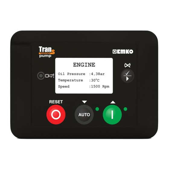
- Page 7 3. Front Panel Description And Accessing To The Parameters 3.1 Front Panel Description ü RESET AUTO Number Comment This LED indicates that any alarm was detected. This LED shows that the unit is in the AUTO mode. In the Manual and Auto modes, this LED indicates that the engine is starting up or is running. This button is used for showing next page in normal operation.In Programming mode it is used for entering parameter edit section, saving parameter value and showing next parameters on the currently selected page.This button will also silence the alarm horn after a...
- Page 8 LCD display Description Generator Page1 Current page name GENERATOR Measurement values V12: 380V I1: 20A ü PF1:-0.84 Fq:50.0Hz On load Engine Status RESET or Error Messages AUTO 128x64 Dot-matrix LCD display. Use the Next button to select which Data display page (screen) is to be displayed. When enter button pressed for 2 seconds, menu options displayed.
- Page 9 Data display pages on the LCD display; Generator Page1: V12: Generator voltage L1-L2 GENERATOR Load Current L1 PF1: V12: 380V I1: 20A Generator power factor L1 Generator frequency PF1:-0.84 Fq:50.0Hz On load Generator Page2: Generator active power GENERATOR Generator reactive power 170kW Generator apparent power 40kVAr...
- Page 10 Engine Maintenance Page: Next hours: The remaining hour for maintenance ENGINE MAINTENANCE Next months: The remaining month for maintenance Last date: Next hours : 5000 The last maintenance date Next months: Last date: 15/02/2011 On load J1939 Values Page1: Engine speed: Engine speed via J1939 J1939 VALUES Oil pressure:...
- Page 11 J1939 DM1 (Active) Faults Page: Spn: Suspect parameter number (e.g. SPN = 110 corresponds to J1939 DM1 FAULTS1 coolant temperature sensor) Fmi: Spn:110 Failure mode identifier (e.g. FMI = 0 means value too high) Occurrence count (if OC = 0, no alarm is present) Fmi:0 Oc:1 The first 10 active alarm messages (Active Diagnostic Trouble...
- Page 12 Example-1: Displaying all Data display pages. GENERATOR GENERATOR GENERATOR V12: 380V I1: 20A 170kW kWh : 30600 PF1:-0.84 Fq:50.0Hz 40kVAr kVArh: 7200 ü ü ü 210kVA On load On load On load ENGINE ENGINE ENGINE Oil Pressure: 4.3bar Conf.AI : 96% Run times Temperature : 30ºC...
- Page 13 Example-2: Displaying all Event Log display pages GENERATOR V12: 380V I1: 20A Program Program PF1:-0.84 Fq:50.0Hz ü Language Language ü ü Event log Event log On load RESET RESET RESET Press Enter button AUTO AUTO AUTO for 2 seconds to access the menu options.
- Page 14 3.2 Accessing To The Operator Parameters PROGRAM OPERATOR SETTING OPERATOR SETTING GENERATOR GENERATOR VOLT LEVEL GENERATOR VOLT LEVEL GENERATOR VOLT LEVEL Operator setting Password Generator Volt level Under volt shutdown Under volt shutdown Under volt shutdown ü ü ü ü ü...
-
Page 15: Accessing To The Technician Parameters
3.3 Accessing To The Technician Parameters PROGRAM TECHNICIAN SETTING TECHNICIAN SETTING SYSTEM SYSTEM NETWORK SYSTEM NETWORK SYSTEM NETWORK Operator setting Password System Network CT ratio CT ratio CT ratio ü ü ü ü ü ü Technician setting Generator Breakers PT ratio 500 A PT ratio Factory adjustment... - Page 16 GEN CUR LEVEL & ACT GEN CUR LEVEL & ACT GEN CUR LEVEL & ACT Over cur. act. Over cur. actions Over cur. act. ü ü Over act. delay time DISBL Over act. delay time Short circuit cur. Short circuit cur. GENERATOR GEN POWER LEVEL GEN POWER LEVEL...
- Page 17 ENGINE CANBUS ECU CANBUS ECU CANBUS ECU CanBus ECU Baud rate Baud rate Baud rate ü ü ü CanBus error set J1939 ECU type J1939 ECU type Maintenance Device address Device address Load test SPN version SPN version AUTO AUTO CANBUS ECU CANBUS ECU CANBUS ECU...
- Page 18 SENDER LINEARISATION SENDER LINEARISATION SENDER LINEARISATION Oil pressure sender 3 Oil pressure sender 3 Oil pressure sender 3 ü ü Oil pressure 3 62 R Oil pressure 3 Oil pressure sender 4 Oil pressure sender 4 Oil pressure 4 Oil pressure 4 AUTO SENDER LINEARISATION SENDER LINEARISATION...
- Page 19 INPUTS CONF. INPUT-3 CONF. INPUT-3 CONF. INPUT-3 Conf. input-3 Dis,user conf.or list Dis,user conf.or list Dis,user conf.or list ü ü ü Polarity Polarity Indication Indication Activation Activation AUTO AUTO CONF. INPUT-3 CONF. INPUT-3 CONF. INPUT-3 Select from list Select from list Select from list ü...
-
Page 20: Changing And Saving Parameter Values
3.4 Changing And Saving Parameters Values Operation Screen GENERATOR PROGRAM V12: 380V I1: 20A Program Operator setting ü PF1:-0.84 Fq:50.0Hz ü Language Technician setting ü Event log Factory adjustment On load RESET RESET RESET AUTO AUTO AUTO Press Enter button Press the Up or Down When the Enter button is for 2 seconds to... -
Page 21: Parameters
4. Parameters 4.1 Operator Parameters 4.1.1 Generator GENERATOR VOLT LEVEL ( Generator-> Volt level Default Unit Under volt shutdown Generator Under Voltage Shutdown 60(dis) Under volt prealarm Generator Under Voltage Pre-Alarm 60(dis) Under volt reset Generator Under Voltage Pre-Alarm Reset Over volt shutdown Generator Over Voltage Shutdown Over volt prealarm... -
Page 22: System
4.2 Technician Parameters 4.2.1 System SYSTEM NETWORK ( System->Network Default Unit CT ratio Current Transformer Ratio 9999 PT ratio Voltage Transformer Ratio Type of AC system Select AC system; 0- 1 Phase 2 Wire 1- 3 Phase 4 Wire 2- 2 Phase 3 Wire L1-L2 3- 2 Phase 3 Wire L1-L3 Generator kVA rating Generator kVA rating set... - Page 23 Example: If Hardware Breaker Selection parameter is selected as 1; For closing For opening Gen. Shalter Gen. Shalter Gen. Closed Out. (NO) t[s] Gen. Closed Out. (NC) t[s] Gen. Shalter Opened Closed 2- User Configured: Gen breaker has only close drive, when want to breaker close, close breaker output on and after 1 sec.
- Page 24 rtNB brCP brCP brCP brCP brCP brCP brCP brCP brCP brCP GCB close sPLD sPLD sPLD command t[s] brOP brOP brOP GbCt GbCt GbCt GbCt GbCt GbCt GbCt GCB open command t[s] Feedback input t[s] GCB fail to close alarm t[s] Example-2: GCB Open Diagram If Hardware Breaker Selection parameter is selected as 3, Gen.
- Page 25 Transfer Time This is used to allow for fixed duration transfer breaks when switching from mains to generator and back. It can be used to ensure that the supply is removed from the load for fixed period of time to allow pumps/motors to come to rest etc.
-
Page 26: Generator
DATE & TIME SET ( Default Unit System->Date & time set ENABL/DISBL ENABL Real time clock enable/disable Year Year Month Month Date Week Day of week Hour Hour Minute Minute Second Second Day of week 1=Monday,2= Tuesday Wednesday Thursday Friday Saturday Sunday DEFAULT SETTINGS (... - Page 27 GENERATOR FREQ LEVEL ( Default Unit Generator-> Frequency level Nominal frequency Nominal Alternator Frequency 30.0 75.0 50.0 Under freq shutdown Generator Under Frequency Shutdown 30.0(dis) 75.0 43.0 Under freq prealarm Generator Under Frequency Pre-Alarm 30.0(dis) 75.0 45.0 Under freq reset Generator Under Frequency Pre-Alarm Reset 30.0 75.0...
-
Page 28: Outputs
GENERATOR GENERAL ( Default Unit Generator->General Sens.option gen.freq ENABL/DISBL ENABL Sensing Options Generator Frq En/Dis Sens.opt.pickup&flywh* 1000 DISBL Sensing Opt Pickup En/Dis & Flywheel All warning are latch ENABL/DISBL DISBL All Warnings Are Latched En/Dis Sensing Options Generator Frq En/Dis ENABLE: Speed sensing will be derived from the generator output frequency. - Page 29 ENG. CRANK DISCONNECT ( Default Unit Engine->Crank disconnect Generator frequency 25.0 75.0 30.0 Crank Disconnect On Gen. Frequency Engine speed 500 6000 Crank Disconnect On Engine RPM Generator volt 60 (dis) 600 Crank Disconnect On Gen. Voltage Alt. Charge volt 6.0 (dis) 30.0 Crank Disconnect On Charge Alt.
- Page 30 CANBUS ECU ( Default Unit Engine->CanBus ECU Baud rate kBaud Baud Rate: 0 - 20 1 - 50 2 - 100 3 - 125 4 - 250 5 - 500 6 - 800 7 - 1.000 J1939 ECU type 0(dis) J1939 ECU Type Selection: 0 - Disable 1 - Standard...
- Page 31 Device Address The unit sends J1939 request and control messages with this ID. It must be changed for different ECU types according to the following table. The ECU listens only to control messages, if they are sent to the correct address. Volvo EMS1, Volvo EDC4, Perkins 1300,...
- Page 32 CANBUS ERROR SET ( Engine->CanBus error set Default Unit CAN fault actions Can Fault Actions: 0- Disable 1- Warning Non-Latching 2- Warning (Alarm Only, No Shutdown) 3- Electrical Trip (Alarm/Off Load Generator Followed By Shutdown After Cooling) 0(dis) 4- Shutdown (Alarm And Shutdown) CAN fault activation Can Fault Activation: 0- Active From Starting...
- Page 33 ENGINE MAINTENANCE ( Unit Default Engine->Maintenance Running hour interval 0(dis) 9999 5000 Hour Running Hours Interval Maint.date interval 0(dis) Month Maintenance Date Interval Eng. stop when maint ENABL/DISBL DISBL Force Engine Shutdown When Maintenance Is Due Eng.running hour(lsb) Engine Running Hour (Lsb) Eng.running hour Engine Running Hour Eng.running hour(msb)
- Page 34 ENGINE GENERAL ( Engine->General Default Unit Fuel selection 0-GAS Engine Fuel Selection 1-DIESEL 1-DIESEL 2-GASOLINE Stop solenoid time Stop Solenoid Time Ignition delay Ignition Delay Gas valve delay Gas Valve Delay Min. of ignition speed 1500 Minimum Ignition Speed Choke time 30.0 Choke Time Engine Fuel (Gas/ Diesel/Gasoline) Selection...
- Page 38 4.2.4 Inputs SENDER INPUTS ( Inputs->Sender inputs Default Unit Oil pressure unit Oil Pressure Unit BAR/PSI/KPA Oil press. input type Oil Pressure Input Type 0 - Not Used (Disable) 1 - Digital NC 2 - Digital NO 3 - VDO 5 BAR 4 - VDO 7 BAR 5 - VDO 10 BAR 6 - DATCON 5 BAR...
- Page 39 Oil Pressure Input Type This section is used to configure the Oil Pressure sender input. 0 NOT USED: The Oil Pressure input will not be monitored. 1 DIGITAL NC: The Oil pressure input is fed from an engine mounted digital pressure switch. This switch returns a closed signal during low oil pressure conditions (and engine at rest), once oil pressure is established the switch will open.
- Page 40 SENDER LINEARISATION ( Inputs->Sender linearisation Default Unit Oil pressure sender 1 1300 Oil Pressure Sender Point-1 Oil pressure 1 30.0 Oil Pressure Point-1 Oil pressure sender 2 1300 Oil Pressure Sender Point-2 Oil pressure 2 30.0 Oil Pressure Point-2 Oil pressure sender 3 1300 Oil Pressure Sender Point-3 Oil pressure 3...
- Page 41 Conf. AI sender 6 1300 Configurable Analog Input Sender Point-6 Conf. AI value 6 3000 Configurable Analog Input Point-6 Conf. AI sender 7 1300 Configurable Analog Input Sender Point-7 Conf. AI value 7 3000 Configurable Analog Input Point-7 Conf. AI sender 8 1300 Configurable Analog Input Sender Point-8 Conf.
- Page 42 CONF. INPUT-1 ( Inputs->Conf. input-1 Default Unit Dis,user conf.or list 0- Disable 0(dis) 1- User Configured 2- Select From List Polarity 0- Normally Open (Close To Activate) 1- Normally Close (Open To Activate) Indication If User Configured 0- Status 1- Warning Non-Latching 2- Warning Latching 3- Electrical Trip 4- Shutdown...
- Page 43 CONF. INPUT-2 ( Inputs->Conf. input-2 Default Unit Dis,user conf.or list 0- Disable 0(dis) 1- User Configured 2- Select From List Polarity 0- Normally Open (Close To Activate) 1- Normally Close (Open To Activate) Indication If User Configured 0- Status 1- Warning Non-Latching 2- Warning Latching 3- Electrical Trip 4- Shutdown...
- Page 44 CONF. INPUT-3 ( Inputs->Conf. input-3 Default Unit Dis,user conf.or list 0- Disable 0(dis) 1- User Configured 2- Select From List Polarity 0- Normally Open (Close To Activate) 1- Normally Close (Open To Activate) Indication If User Configured 0- Status 1- Warning Non-Latching 2- Warning Latching 3- Electrical Trip 4- Shutdown...
- Page 45 CONFIGURABLE INPUTS SELECTIONS 0 REMOTE START ON LOAD In AUTO mode, if one of the configurable inputs are selected as 0 (Remote Start On Load) and this input is active, then the unit will perform the start sequence and transfer load to the generator. If the input is passive, the unit will perform the stop sequence.
- Page 46 17 PANEL LOCK This input is used to provide security to the installation. If the panel lock input is active, the unit will not respond to operation of the mode select or start buttons. This allows the unit to be placed into a spesific mode (such as Auto) and than secured.
- Page 47 4.2.5 Outputs CONF. OUTPUT-1 ( Outputs->Conf. output-1 Default Unit Polarity 0- Normally Open (Close To Activate) 1- Normally Close (Open To Activate) Function 0-NOT USED 1-AIR FLAP CONTROL 2-ALARM RESET 3-AUDIBLE ALARM 4-AUTO START INHIBIT 5-RESERVED 6-BATTERY HIGH VOLTAGE 7-BATTERY LOW VOLTAGE 8-RESERVED 9-CAN ECU POWER (only available at Trans-MiniAUTO.CAN) 10-CAN ECU STOP (only available at Trans-MiniAUTO.CAN)
- Page 48 CONF. OUTPUT-2 ( Outputs->Conf. output-2 Default Unit Polarity 0- Normally Open (Close To Activate) 1- Normally Close (Open To Activate) Function The same as Configurable Output-1 options CONF. OUTPUT-3 ( Outputs->Conf. output-3 Default Unit Polarity 0- Normally Open (Close To Activate) 1- Normally Close (Open To Activate) Function The same as Configurable Output-1 options...
- Page 49 CONFIGURABLE OUTPUTS SELECTIONS 0 NOT USED Output is not used 1 AIR FLAP CONTROL Normally used to control an air flap, this output becomes active upon an Engine shutdown failure situation. Inactive when the set has come to rest. 2 ALARM RESET The output indicates that an alarm reset being performed.
- Page 50 18 COOLANT TEMPERATURE HIGH PRE-ALARM This output indicates that a high engine coolant temperature warning (pre-alarm) has occurred. 19 COOLANT TEMPERATURE HIGH SHUTDOWN This output indicates that a high engine coolant temperature shutdown has occurred. 20 COOLING DOWN TIMER IN PROGRESS This output source will be active when the cooling off-load timer is running.
- Page 51 44 GAS ENGINE IGNITION OUTPUT With the engaging of the starter the ignition delay is started. If the ‘minimum ignition speed’ is reached after expiry of this time, the configurable relay output ‘ignition’ is set. When the necessary engine shutdown process, firstly gas valve is de-energised.
- Page 52 65 LOSS OF MAGNETIC PICK-UP SPEED SIGNAL(only available at Trans-MiniAUTO.MPU) This output indicates that the magnetic pick up signal is not sufficient to be used by the unit for speed monitoring. The alarm can only operate if the speed signal fails to appearduring cranking. It is disabled if ‘multiple attempts to engage’...
- Page 53 89 PANEL LOCK This output indicates that the unit ‘panel lock’ is active. If the panel lock input is active, the unit will not respond to operation of the Mode select or start buttons. This allows the unit to be placed into a specific mode (such as auto) and then secured.
- Page 54 107 UNDER POWER PRE-ALARM This output indicates that the under power pre-alarm has been reached. 108 UNDER POWER SHUTDOWN This output indicates that the under power shutdown has been reached. 109 UNDER SPEED PRE-ALARM This output indicates that an under speed warning (pre-alarm) has occurred. 110 UNDER SPEED SHUTDOWN This output indicates that an under speed shutdown has occurred.
- Page 55 4.2.6 Timers START TIMERS ( Unit Default Timers->Start timers Remote start delay 3600 Remote Start Delay Pre-heat Pre-Heat Pre-heat bypass Pre-Heat Bypass Safety on delay Safety On Delay Warming up time Warmup Time Horn duration 0 (dis) Horn Duration Chg. excitation time 0 99(cont) Charge Excitation Time Cooling fan time...
- Page 56 Cooling Fan Time This timer dictates how long the Cooling Fan will continue to operate. Idle Mode Time (Smoke Limiting) This is the amount of time that the smoke limiting output will remain active for once the engine has started. While the smoke limiting output is active the engine will be held at a reduced speed to minimise smoke emissions on start-up.
-
Page 57: User Adjustment
4.2.7 User Adjustment GEN. VOLTAGE OFFSET ( Default Unit User adjustment->Gen. voltage offset Gen. V1 offset Generator V1 Offset CURRENT OFFSET ( Default Unit User adjustment-> Current offset Current I1 offset Current I1 Offset BATTERY&CHRG GEN.VOL & Default Unit User adjustment->Battery chrg gen vol Batt.volt offset Battery Voltage Offset Gen.chg.volt offset... - Page 58 Error Messages And Explanations: Battery high warning! : Battery high error Battery low warning! : Battery low error Can bus warning! : Can bus error (Only available at Trans-MiniAUTO.CAN devices) Charge alterntr fail! : Caharge alternator fail Conf. AI low error! : Configurable analogue input low error Conf.
- Page 59 Event Messages And Explanations: Battery high warning : Battery high error Battery low warning : Battery low error Can bus warning : Can bus error (Only available at Trans-MiniAUTO.CAN devices) Changed mode to auto : Changed mode to auto Changed mode to man : Changed mode to manual Changed mode to stop : Changed mode to stop...
-
Page 60: Specifications
5. Specifications Equipment use : Electrical control equipment for generating sets. Housing & Mounting :111 mm x 81 mm x 61 mm. (including connectors) . Plastic housing for panel mounting Panel Cut-Out : 81mm x 70mm. Protection IP65 at front panel. Weight : Approximately 0,3 Kg. -
Page 61: Other Informations
Emko Elektronik Sanayi ve Ticaret A.Þ. Demirtaþ Organize Sanayi Bölgesi Karanfil Sk. No:6 16369 BURSA/TURKEY Phone : +90 224 261 1900 Fax : +90 224 261 1912 Thank you very much for your preference to use Emko Elektronik Products. Your Technology Partner www.emkoelektronik.com.tr...
Need help?
Do you have a question about the TRANS MINI AUTO and is the answer not in the manual?
Questions and answers