Table of Contents
Advertisement
FOR GAS/DIESEL/GASOLINE GENERATORS
EMKO ELEKTRON K A. .
Ý
Demirta Org. San. Bolg.
þ
Karanfil Sk. No: 6 TR
16369 Bursa / TURKEY
Phone
: +90 224 261 1900
Faks
: +90 224 261 1912
Url
: www.emkoelektronik.com.tr
E-mail
:emko@emkoelektronik.com.tr
exposales@emkoelektronik.com.tr
TRANS-AMF
AUTOMATIC MAINS FAILURE UNIT
WITH J1939 ECUs
User Manual
Þ
Introduction Manual. ENG TRANS-AMF 02 V28 09/15
Advertisement
Table of Contents

Related Manuals for EMKO TRANS-AMF


Summary of Contents for EMKO TRANS-AMF
- Page 1 Ý Þ Demirta Org. San. Bolg. þ Karanfil Sk. No: 6 TR 16369 Bursa / TURKEY Phone : +90 224 261 1900 Faks : +90 224 261 1912 : www.emkoelektronik.com.tr E-mail :emko@emkoelektronik.com.tr exposales@emkoelektronik.com.tr Introduction Manual. ENG TRANS-AMF 02 V28 09/15...
-
Page 2: Table Of Contents
CONTENTS 1.Introduction............................Page 1.1 General Specifications......................Page 1.2 Warranty............................ Page 1.3 Maintenance ..........................Page 2.Installation............................Page 2.1 Unit Configuration........................Page 2.2 Panel Mounting.......................... Page Figure 2.1 Front View........................ Page Figure 2.2 Panel Cut-Out......................Page 2.3 Electrical Connection......................... Page 3.Definition Of Front Panel And Accessing To The Parameters............Page 3.1 Front Panel Description...................... - Page 3 EU DECLARATION OF CONFORMITY Manufacturer’s Name : EMKO ELEKTRONIK A.S. Manufacturer’s Address : DOSAB, Karanfil Sk., No:6, 16369 Bursa, TURKEY The manufacturer hereby declares that the product: Product Name : Automatic Mains Failure Unit Type Number : TRANS-AMF Product Category...
-
Page 4: Introduction
The configurable input-7 can be used as the cabin temperature analog input. 1.2 Warranty EMKO Elektronik warrants that the equipment delivered is free from defects in material and workmanship. This warranty is provided for a period of two years. The warranty period starts from the delivery date. -
Page 5: Installation
2. Installation Ýçindekiler Before beginning installation of this product, please read the instruction manual and warnings below carefully. A visual inspection of this product for possible damage occured during shipment is recommended before installation. It is your responsibility to ensure that qualified mechanical and electrical technicians install this product. -
Page 6: Electrical Connection
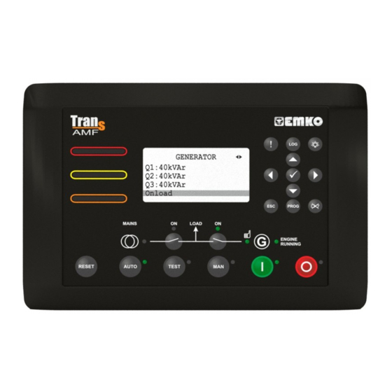
2.3 Electrical Connection TRANS-AMF three phase connections schematic BATTERY - FUSE-7 BATTERY + Configurable Analog Input-2 Oil Sender Temperature Sender Level Sender or Configurable Analog Input-1 To Engine Sender Common Earth Emergency Stop or FUSE-6 Configurable Input-1 FUSE-5 Configurable Input-2... - Page 7 3. Front Panel Description And Accessing To The Parameters 3.1 Front Panel Description 15 16 17 Number Comment This LED indicates that a "Shutdown" alarm was detected. This LED indicates that a "Warning" alarm was detected This LED indicates that a "Maintenance" alarm was detected This LCD display is used for displaying the electrical measurements during normal operation, and editing/inspecting programming parameters in program mode.
- Page 8 Number Comment Warning and Alarm messages shortcut button. Event Logs shortcut button. The LAMP TEST button illuminates all LED indicators. This button is used for showing previous parameters on the currently selected page in normal operation. In Programming mode, it operates as an Up button (changing cursor position) or Increment button (increase parameter value).
- Page 9 Data display pages on the LCD display; Mains Page1: V12: Mains voltage L1-L2 MAINS V23: Mains voltage L2-L3 V31: Mains voltage L3-L1 V12: 380V V1: 220V V1: Mains voltage L1-N V23: 380V V2: 220V V2: Mains voltage L2-N V31: 380V V3: 220V V3: Mains voltage L3-N Wait for start Mains Page2:...
- Page 10 Generator Page5: Q1: Generator reactive power L1 GENERATOR Q2: Generator reactive power L2 Q3: Generator reactive power L3 40kVAr 40kVAr 40kVAr On load Generator Page6: S1: Generator apparent power L1 GENERATOR S2: Generator apparent power L2 S3: Generator apparent power L3 210kVA 210kVA 210kVA...
- Page 11 Engine Page3: Gen.chg.volt: Charge generator voltage ENGINE Run times: Number of generator runs Crank times: Number of generator starts Gen.chg.volt: 11.8Vdc Run times Crank times : On load Engine Page4: W.Hour_Min: Engine running time (Hour and Minute) ENGINE Cabin temp: Cabin temperature W.Hour_Min: 2_57 Cabin temp:...
- Page 12 J1939 Values Page4: Oil temper.: Oil temperature via J1939 J1939 VALUES Act.engine torq: Actual engine torque via J1939 Boost press.: Boost pressure via J1939 Oil temper.: 82.00ºC Act.engine torq: 75% Boost press.: 2.8bar On load J1939 Values Page5: Int.man.temp.: Intake manifold temperature via J1939 J1939 VALUES Pedal position: Accelerator pedal position via J1939 W.Hour_Min: Working hour and minute via J1939...
- Page 13 GenSet Page: (This page is only available at TRANS-AMF.TR device) VLn: Generator voltage L1-N, L2-N and L3-N GENSET Amp: Generator current L1, L2 and L3 220V 220V 220V Hz: Generator frequency bar: Oil pressure sender input value 50.0Hz 4.3bar kW: Generator total active power 630kW 30ºC...
- Page 14 Example-1: Displaying all Data display pages. MAINS MAINS GENERATOR V12: 380V V1: 220V Fq:50.0Hz V12: 380V V1: 220V V23: 380V V2: 220V Phase seq.: L1 L2 L3 V23: 380V V2: 220V V31: 380V V3: 220V V31: 380V V3: 220V Wait for start Wait for start On load GENERATOR...
- Page 15 Example-2: Displaying all Warning&Alarm display pages WARNING&ALARM 1/2 WARNING&ALARM 2/2 Emergency stop! High temp.prealarm! MAINS V12: 380V V1: 220V V23: 380V V2: 220V V31: 380V V3: 220V Wait for start Example-3: Displaying all Event Log display pages EVENT LOG 1.1 EVENT LOG 1.2 EVENT LOG 1.3 15/02/2011...
- Page 16 3.2 Accessing To The Operator Parameters PROGRAM OPERATOR SETTING OPERATOR SETTING MAINS MAINS VOLT LEVEL MAINS VOLT LEVEL MAINS VOLT LEVEL Operator setting Password Mains Volt level Under volt trip Under volt trip Under volt trip Technician setting Generator Frequency level Under volt reset 320 Vac Under volt reset...
- Page 17 3.3 Accessing To The Technician Parameters PROGRAM TECHNICIAN SETTING TECHNICIAN SETTING SYSTEM SYSTEM NETWORK SYSTEM NETWORK SYSTEM NETWORK Operator setting Password System Network CT ratio CT ratio CT ratio Technician setting Mains Breakers Earth Fault CT ratio 500 A Earth Fault CT ratio Factory adjustment 0000 Generator...
- Page 18 GENERATOR VOLT LEVEL GENERATOR VOLT LEVEL GENERATOR VOLT LEVEL Over volt prealarm Over volt prealarm Over volt prealarm Over volt reset 340 Vac Over volt reset Shutdown delay time Shutdown delay time GENERATOR GENERATOR FREQ LEVEL GENERATOR FREQ LEVEL GENERATOR FREQ LEVEL Volt level Nominal frequency Nominal frequency...
- Page 19 ENGINE START OPTIONS ENGINE START OPTIONS ENGINE START OPTIONS Pickup fail delay Pickup fail delay Pickup fail delay 1.0 sec ENGINE ENG.CRANK DISCONNECT ENG.CRANK DISCONNECT ENG.CRANK DISCONNECT Starting options Generator frequency Generator frequency Generator frequency Crank disconnect Engine speed 30.0 Hz Engine speed Speed settings Generator volt...
- Page 20 EXERCISE EXERCISE EXERCISE Stop time on Thursday Stop time on Thursday Stop time on Thursday Start time on Friday 0.00 Hour.Min Start time on Friday Stop time on Friday Stop time on Friday Start time on satur. Start time on satur. EXERCISE EXERCISE EXERCISE...
- Page 21 SENDER LINEARISATION SENDER LINEARISATION SENDER LINEARISATION Temperature sender 1 Temperature sender 1 Temperature sender 1 Temperature 1 360 R Temperature 1 Temperature sender 2 Temperature sender 2 Temperature 2 Temperature 2 SENDER LINEARISATION SENDER LINEARISATION SENDER LINEARISATION Temperature sender 3 Temperature sender 3 Temperature sender 3 Temperature 3...
- Page 22 INPUTS CONF. INPUT-2 CONF. INPUT-2 CONF. INPUT-2 Sender inputs Dis,user conf.or list Dis,user conf.or list Dis,user conf.or list Sender linearisations Polarity Polarity Conf. input-1 Indication Indication Conf. input-2 Activation Activation CONF. INPUT-2 CONF. INPUT-2 CONF. INPUT-2 Select from list Select from list Select from list Active delay 3-SIM.LAMP TEST BUT...
- Page 23 TECHNICIAN SETTING EXPANSION MODULES IO (1-8) MODULE IO (1-8) MODULE IO (1-8) MODULE Inputs IO (1-8) Disable/enable select Disable/enable select Disable/enable select Outputs Dial-up & Ethernet DISBL Timers Expansion modules GPRS EXPANSION MODULES DIAL-UP & ETHERNET DIAL-UP & ETHERNET DIAL-UP & ETHERNET IO (1-8) Disable/enable select Disable/enable select...
- Page 24 3.4 Changing And Saving Parameters Values Operation Screen MAINS PROGRAM V12: 380V V1: 220V Operator setting Press the Up or V23: 380V V2: 220V Technician setting Down buttons to V31: 380V V3: 220V Factory adjustment select the section Wait for start you wish to view/change.
-
Page 25: Parameters
4. Parameters 4.1 Operator Parameters 4.1.1 Mains MAINS VOLT LEVEL (Mains->Volt level) Default Unit Under volt trip Mains Under Voltage Under volt reset Mains Under Voltage Reset Over volt trip Mains Over Voltage Over volt reset Mains Over Voltage Reset MAINS FREQ. - Page 26 GEN POWER LEVEL (Generator->Power level) Default Unit Under power set Generator Under Power Set 9999 Under power prealarm Generator Under Power Pre-Alarm 0(dis) 9999 Under power reset Generator Under Power Pre-Alarm Reset 9999 Over power IDMT alarm Generator Over Power IDMT Alarm ENABL/DISBL DISBL Over power set...
-
Page 27: System
4.2 Technician Parameters 4.2.1 System SYSTEM NETWORK (System->Network) Default Unit CT ratio Current Transformer Ratio 9999 Earth fault CT ratio Earth Fault Current Transformer Ratio 9999 PT ratio Voltage Transformer Ratio 0- 1 Phase 2 Wire Type of AC system Select AC system;... - Page 28 Example: If Hardware Breaker Selection parameter is selected as 0; For closing For opening Gen. Shalter Gen. Shalter Gen. Closed Out. (NO) t[s] Gen. Closed Out. (NC) t[s] Opened Gen. Shalter Closed 1- User Configured: Mains and Gen breakers have only close drives, when want to breaker close, close breaker output on and after 1 sec.
- Page 29 rtNB brCP brCP brCP brCP brCP brCP brCP brCP brCP brCP GCB close sPLD sPLD sPLD command t[s] brOP brOP brOP GbCt GbCt GbCt GbCt GbCt GbCt GbCt GCB open command t[s] Feedback input t[s] GCB fail to close alarm t[s] Example-2: GCB Open Diagram.
- Page 30 Mains Open Timer This is used to monitor the opening of the mains contactor or breaker. It will only operate if an auxiliary input is configured as ‘Mains Closed Auxiliary’ and connected to the auxiliary on the mains contactor or breaker.
- Page 31 Default Unit COMMUNICATION (System->Communication) Slave address Slave Address Baud rate Baud Rate: 0 - 1200 baud 1 - 2400 baud 2 - 4800 baud 3 - 9600 baud 4 - 19200 baud 5 - 38400 baud Parity Parity: 0 - NONE 1 - ODD 2 - EVEN Stop bit...
-
Page 32: Engine
4.2.2 Mains MAINS VOLT LEVEL (Mains->Volt level) Default Unit Under volt trip Mains Under Voltage Under volt reset Mains Under Voltage Reset Over volt trip Mains Over Voltage Over volt reset Mains Over Voltage Reset MAINS FREQ. LEVEL (Mains-> level) Default Unit Frequency... - Page 33 GEN CUR LEVEL & ACT (Generator->Current level & act.) Default Unit Under cur. set 9999 Generator Under Current Set Under cur. prealarm Generator Under Current Pre-Alarm 0(dis) 9999 Under cur. reset Generator Under Current Pre-Alarm Reset 9999 Under cur. act. Generator Under Current Actions 0(dis) 0 - Disable...
- Page 34 GEN POWER LEVEL (Generator->Power level) Default Unit Under power set Generator Under Power Set 9999 Under power prealarm Generator Under Power Pre-Alarm 0(dis) 9999 Under power reset Generator Under Power Pre-Alarm Reset 9999 Under power act. 0(dis) 0(dis) Generator Under Power Actions 0 - Disable 1 - Warning (Alarm Only, No Shutdown) 2 - Electrical Trip (Alarm/Off Load Generator...
-
Page 35: Inputs
GENERATOR GENERAL (Generator->General) Default Unit Sens.option gen.freq ENABL/DISBL ENABL Sensing Options Generator Frq En/Dis Sens.opt.pickup&flywh 1000 DISBL Sensing Opt Pickup En/Dis & Flywheel All warning are latch ENABL/DISBL DISBL All Warnings Are Latched En/Dis Sensing Options Generator Frq En/Dis ENABLE: Speed sensing will be derived from the generator output frequency. DISABLE: Speed sensing not will be derived from the generator output frequency. - Page 36 ENG. CRANK DISCONNECT (Engine->Crank disconnect) Default Unit Generator frequency 10.0 75.0 30.0 Crank Disconnect On Gen. Frequency Engine speed 100 6000 Crank Disconnect On Engine RPM Generator volt 60 (dis) 600 Crank Disconnect On Gen. Voltage Charge alt. volt 6.0 (dis) 30.0 Crank Disconnect On Charge Alt.
- Page 37 ENGINE PLANT BATTERY (Engine->Plant battery) Unit Default 6.0(dis) 30.0 Under volt shutdown Battery Undervolts Shutdown Under volt warning 6.0(dis) 30.0 11.0 Battery Undervolts Warning Under volt reset 30.0 11.5 Battery Undervolts Warning Reset Under volt delay Battery Undervolts Volts Delay Over volt shutdown 6.0(dis) 30.0...
- Page 38 CANBUS ECU (Engine->CanBus ECU) Unit Default Baud rate kBaud Baud Rate: 0 - 20 1 - 50 2 - 100 3 - 125 4 - 250 5 - 500 6 - 800 7 - 1.000 J1939 ECU type 0(dis) J1939 ECU Type Selection: 0 - Disable 1 - Standard 2 - Volvo EMS1...
- Page 39 Device Address The unit sends J1939 request and control messages with this ID. It must be changed for different ECU types according to the following table. The ECU listens only to control messages, if they are sent to the correct address. Volvo EMS1, Volvo EDC4, Perkins 1300,...
- Page 40 CANBUS ERROR SET (Engine->CanBus error set) Unit Default CAN fault actions Can Fault Actions: 0- Disable 1- Warning Non-Latching 2- Warning (Alarm Only, No Shutdown) 3- Electrical Trip (Alarm/Off Load Generator Followed By Shutdown After Cooling) 0(dis) 4- Shutdown (Alarm And Shutdown) CAN fault activation Can Fault Activation: 0- Active From Starting...
- Page 41 ENGINE MAINTENANCE (Engine->Maintenance) Unit Default Running hour interval 0(dis) 9999 5000 Hour Running Hours Interval Maint. date interval 0(dis) Month Maintenance Date Interval ENABL/DISBL DISBL Eng. stop when maint Force Engine Shutdown When Maintenance Is Due Eng. running hour(lsb) Engine Running Hour (Lsb) Eng.
- Page 42 EXERCISE (Engine->Exercise) Default Unit Disable/enable select Exercise Disable or Enable DISBL/ENABL DISBL Start time1 on monday 0.00 23.59 0.00 H.Min Exercise Sta rt Time 1 on Monday Stop time1 on monday 0.00 23.59 0.00 H.Min Exercise Stop Time 1 on Monday Start time2 on monday Exercise Start Time 2 on Monday 0.00...
- Page 43 Start time1 on sunday Exercise Sta rt Time 1 on Sunday 0.00 23.59 0.00 H.Min Stop time1 on sunday 0.00 23.59 0.00 H.Min Exercise Stop Time 1 on Sunday Start time2 on sunday 0.00 23.59 0.00 H.Min Exercise Sta rt Time 2 on Sunday Stop time2 on sunday Exercise Stop Time 2 on Sunday 0.00...
- Page 44 ENGINE GENERAL (Engine->General) Default Unit 0-GAS Fuel selection Engine Fuel Selection 1-DIESEL 1-DIESEL 2-GASOLINE Stop solenoid time Stop Solenoid Time Ignition delay Ignition Delay Gas valve delay Gas Valve Delay Min. of ignition speed 1500 Minimum Ignition Speed Choke time 30.0 Choke Time Engine Fuel (Gas/ Diesel/Gasoline) Selection...
- Page 48 4.2.5 Inputs SENDER INPUTS (Inputs->Sender inputs) Default Unit Oil pressure unit Oil Pressure Unit BAR/PSI/KPA Oil press. input type Oil Pressure Input Type 0 - Not Used (Disable) 0 (dis) 1 - Digital NC 2 - Digital NO 3 - VDO 5 BAR 4 - VDO 7 BAR 5 - VDO 10 BAR 6 - DATCON 5 BAR...
- Page 49 Configurable Analog Input-1 Conf. AI1 high shutd. 0 (dis) 3000 0 (dis) High Shutdown Configurable Analog Input-1 Conf. AI1 control ON 0 (dis) 3000 0 (dis) control ON Conf. AI1 control OFF 3000 Configurable Analog Input-1 control OFF Conf. AI2 unit Configurable Analog Input-2 Unit ºC BAR/PSI/KPA/ºC/ºF/%/Lt...
- Page 50 Oil Pressure Input Type This section is used to configure the Oil Pressure sender input. 0 NOT USED: The Oil Pressure input will not be monitored. 1 DIGITAL NC: The Oil pressure input is fed from an engine mounted digital pressure switch. This switch returns a closed signal during low oil pressure conditions (and engine at rest), once oil pressure is established the switch will open.
- Page 51 SENDER LINEARISATION (Inputs->Sender linearisation) Default Unit 1300 Oil pressure sender 1 Oil Pressure Sender Point-1 Oil pressure 1 30.0 Oil Pressure Point-1 1300 Oil pressure sender 2 Oil Pressure Sender Point-2 30.0 Oil pressure 2 Oil Pressure Point-2 1300 Oil pressure sender 3 Oil Pressure Sender Point-3 Oil pressure 3 30.0...
- Page 52 1300 Conf. AI1 sender 6 Configurable Analog Input-1 Sender Point-6 Conf. AI1 value 6 3000 Configurable Analog Input-1 Point-6 1300 Conf. AI1 sender 7 Configurable Analog Input-1 Sender Point-7 Conf. AI1 value 7 3000 Configurable Analog Input-1 Point-7 1300 Conf. AI1 sender 8 Configurable Analog Input-1 Sender Point-8 Conf.
- Page 53 CONF. INPUT-1 (Inputs->Conf. input-1) Default Unit Dis,user conf.or list 0- Disable 0(dis) 1- User Configured 2- Select From List Polarity 0- Normally Open (Close To Activate) 1- Normally Close (Open To Activate) Indication If User Configured 0- Status 1- Warning Non-Latching 2- Warning Latching 3- Electrical Trip 4- Shutdown...
- Page 54 CONF. INPUT-2 (Inputs->Conf. input-2) Default Unit Dis,user conf.or list 0- Disable 0(dis) 1- User Configured 2- Select From List Polarity 0- Normally Open (Close To Activate) 1- Normally Close (Open To Activate) Indication If User Configured 0- Status 1- Warning Non-Latching 2- Warning Latching 3- Electrical Trip 4- Shutdown...
- Page 55 CONF. INPUT-3 (Inputs->Conf. input-3) Default Unit Dis,user conf.or list 0- Disable 0(dis) 1- User Configured 2- Select From List Polarity 0- Normally Open (Close To Activate) 1- Normally Close (Open To Activate) Indication If User Configured 0- Status 1- Warning Non-Latching 2- Warning Latching 3- Electrical Trip 4- Shutdown...
- Page 56 CONF. INPUT-4 (Inputs->Conf. input-4) Default Unit Dis,user conf.or list 0- Disable 0(dis) 1- User Configured 2- Select From List Polarity 0- Normally Open (Close To Activate) 1- Normally Close (Open To Activate) Indication If User Configured 0- Status 1- Warning Non-Latching 2- Warning Latching 3- Electrical Trip 4- Shutdown...
- Page 57 CONF. INPUT-5 (Inputs->Conf. input-5) Default Unit Dis,user conf.or list 0- Disable 0(dis) 1- User Configured 2- Select From List Polarity 0- Normally Open (Close To Activate) 1- Normally Close (Open To Activate) Indication If User Configured 0- Status 1- Warning Non-Latching 2- Warning Latching 3- Electrical Trip 4- Shutdown...
- Page 58 CONF. INPUT-6 (Inputs->Conf. input-6) Default Unit Dis,user conf.or list 0- Disable 0(dis) 1- User Configured 2- Select From List Polarity 0- Normally Open (Close To Activate) 1- Normally Close (Open To Activate) Indication If User Configured 0- Status 1- Warning Non-Latching 2- Warning Latching 3- Electrical Trip 4- Shutdown...
- Page 59 CONF. INPUT-7 (Inputs->Conf. input-7) Default Unit Input type 0- Disable 0(dis) 1- User Configured (Digital) 2- Select From List (Digital) 3- Cabin Temperature (Anolog) Polarity If Input Type is Digital 0- Normally Open (Close To Activate) 1- Normally Close (Open To Activate) Indication If Input Type is User Configured 0- Status...
- Page 60 CONF. EXP. INPUT-1 (Inputs->Conf. exp. input-1) Default Unit Dis,user conf.or list 0- Disable 0(dis) 1- User Configured 2- Select From List Hardware type 0-> -Ve (Switched To Battery -) 1-> +Ve (Switched To Battery +) Polarity 0- Normally Open (Close To Activate) 1- Normally Close (Open To Activate) Indication If User Configured...
- Page 61 CONF. EXP. INPUT-4 (Inputs->Conf. exp. input-4) Default Unit Dis,user conf.or list The same as Expansion Config. Input-1 options 0(dis) The same as Expansion Config. Input-1 options Hardware type Polarity The same as Expansion Config. Input-1 options Indication The same as Expansion Config. Input-1 options Activation The same as Expansion Config.
- Page 62 CONFIGURABLE INPUTS SELECTIONS 0 REMOTE START ON LOAD In AUTO mode, if one of the configurable inputs are selected as 0 (Remote Start On Load), the unit doesn't perform the mains failure control in order to start the generator. In AUTO mode, if one of the configurable inputs are selected as 0 (Remote Start On Load) and this input is active, then the unit will perform the start sequence and transfer load to the generator.
- Page 63 14 MAINS LOAD INHIBIT This input is used to prevent the unit from loading the mains supply. If the manis supply is already on load, activating this input will cause the unit to unload the mains supply. Removing the input will allow the mains to be loaded again.
- Page 64 4.2.6 Outputs CONF. OUTPUT-1 (Outputs->Conf. output-1) Default Unit Polarity 0- Normally Open (Close To Activate) 1- Normally Close (Open To Activate) Function 0-NOT USED 1-AIR FLAP CONTROL 2-ALARM RESET 3-AUDIBLE ALARM 4-AUTO START INHIBIT 5-AUXILIARY MAINS FAILURE 6-BATTERY HIGH VOLTAGE 7-BATTERY LOW VOLTAGE 8-CALLING FOR SCHEDULED RUN(EXERCISE) 9-CAN ECU POWER...
- Page 65 CONF. OUTPUT-2 (Outputs->Conf. output-2) Default Unit Polarity 0- Normally Open (Close To Activate) 1- Normally Close (Open To Activate) Function The same as Configurable Output-1 options CONF. OUTPUT-3 (Outputs->Conf. output-3) Default Unit Polarity 0- Normally Open (Close To Activate) 1- Normally Close (Open To Activate) Function The same as Configurable Output-1 options CONF.
- Page 66 CONF. EXP. OUTPUT-7 (Outputs->Conf. exp. output-7) Default Unit Polarity 0- Normally Open (Close To Activate) 1- Normally Close (Open To Activate) Function The same as Configurable Output-1 options CONF. EXP. OUTPUT-8 (Outputs->Conf. exp. output-8) Default Unit Polarity 0- Normally Open (Close To Activate) 1- Normally Close (Open To Activate) Function The same as Configurable Output-1 options...
- Page 67 15 COMMON WARNING ALARM This output indicates that a warning alarm has been activated. This output is normally self-resetting on removal of the fault. 16 COOLING FAN AFTER START This output should energise as soon as engine has started so the fan should be running when the engine is running.
- Page 68 37 EXPANSION CONFIGURABLE INPUT8 ALARM This output indicates that expansion configurable input 8 alarm has occurred. 38 EARTH FAULT This output indicates that the unit has detected that an earth fault exists on the generator output. 39 EMERGENCY STOP This output indicates that an emergency stop alarm has occurred. 40 FAIL TO START ALARM This output indicates that the engine has not started after the specified number of attempts.
- Page 69 57 GENERATOR LOW VOLTAGE PRE-ALARM This output indicates that a generator low voltage warning (pre-alarm) has occurred. 58 GENERATOR LOW VOLTAGE SHUTDOWN This output indicates that a generator low voltage shutdown has occurred. 59 GENERATOR STOPPING This output indicates that the engine has been instructed to stop but has not come to rest. 60 GENERATOR OPEN BREAKER This output used to control the load switching device.
- Page 70 75 MAINS LOW FREQUENCY This output indicates that the unit has sensed that the incoming AC mains supply frequency has fallen below the frequency setting. 76 MAINS LOW VOLTAGE This output indicates that the unit has sensed that the incoming AC mains supply voltage has fallen below the voltage limit setting.
- Page 71 94 REMOTE START PRESENT This output indicates that a digital input that has been configured as 'remote start' is active. This output could be used to pass the remote start signal on to else where in the control system. 95 REMOTE STOP DELAY IN PROGRESS This output source will be active to indicate that the return timer is running.
- Page 72 114 LOAD SUPPLY FROM MAINS This output indicates that the load is supplying from mains. 115 CONFIGURABLE ANALOG INPUT-1 LOW PRE-ALARM This output indicates that a low configurable analog input-1 warning (pre-alarm) has occurred. 116 CONFIGURABLE ANALOG INPUT-1 LOW SHUTDOWN This output indicates that a low analog input-1 shutdown has occurred.
-
Page 73: Timers
4.2.7 Timers START TIMERS (Timers->Start timers) Unit Default 20.0 Mains transient delay Mains Transient Delay Mains fail start dely 9999 Mains Fail Start Delay Remote start delay 3600 Remote Start Delay Pre-heat Pre-Heat Pre-heat bypass Pre-Heat Bypass Safety on delay Safety On Delay Warming up time Warmup Time... - Page 74 Cooling Fan Time This timer dictates how long the Cooling Fan will continue to operate. Idle Mode Time (Smoke Limiting) This is the amount of time that the smoke limiting output will remain active for once the engine has started. While the smoke limiting output is active the engine will be held at a reduced speed to minimise smoke emissions on start-up.
- Page 75 Unit Default GPRS MODULE (Expansion modules->GPRS) 0-DISABLE 1-SERVER Disable/enable select Expansion GPRS Module Selection 1-SERVER 2-CLIENT Call back selection ENABL/DISBL DISBL Call Back Selection ENABL/DISBL DISBL GPS Feature Enable or Disable Default Unit DUAL SET MODULE (Expansion modules->Dual set) ENABL/DISBL Disable/enable select ENABL Expansion Dual Set Module Selection...
- Page 76 Error Messages And Explanations: Battery high error! : Battery high error Battery low error! : Battery low error Battery high warning! : Battery high error Battery low warning! : Battery low error Cab temp.high error! : Cabin temperature high error Cab temp.high prealr! : Cabin temperature high pre-alarm Cab temp.low error! : Cabin temperature low error Cab temp.low prealr! : Cabin temperature low pre-alarm...
- Page 77 Error Messages And Explanations: Pressure prealarm! : Pressure prealarm Pressure sensor err! : Oil pressure sensor break Red stop lamp! : Red stop lamp error Reverse power warnng! : Reverse power Warning Rev.power trip cool.! : Reverse power Electrical Trip Reverse power trip! : Reverse power Error Short circuit trip! : Short circuit error Spare-1 alarm! : Spare 1 error...
- Page 78 Event Messages And Explanations: Exp.spare-7 alarm : Expansion module spare 7 error Exp.spare-8 alarm : Expansion module spare 8 error Fail to start alarm : Fail to start alarm Gen break.close fail : Generator breaker not closed alarm Gen break.open fail : Generator breaker not opened alarm Gen over frq.prealr : Generator over frequency pre-alarm Gen over frq.shutdwn : Generator over frequency shutdown Gen over vol.prealr : Generator over voltage pre-alarm...
-
Page 79: Specifications
5. Specifications Equipment use : Electrical control equipment for generating sets. Housing & Mounting : 229 mm x 152 mm x 41 mm. (including connectors). Plastic housing for panel mounting. Panel Cut-Out : 182mm x 135mm. Protection : IP65 at front panel. Weight : Approximately 0,53 Kg. -
Page 80: Other Informations
Emko Elektronik Sanayi ve Ticaret A.Þ. Demirtaþ Organize Sanayi Bölgesi Karanfil Sk. No:6 16369 BURSA/TURKEY Phone : +90 224 261 1900 Fax : +90 224 261 1912 Thank you very much for your preference to use Emko Elektronik Products. Your Technology Partner www.emkoelektronik.com.tr...
Need help?
Do you have a question about the TRANS-AMF and is the answer not in the manual?
Questions and answers
Hi please inform about find password Or reset pasword