
Related Manuals for Oakton CON550


Summary of Contents for Oakton CON550
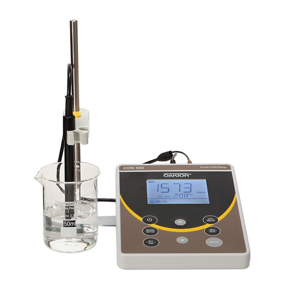
- Page 1 CON550 Benchtop Conductivity Meter Instruction Manual OAKTON INSTRUMENTS www.4oakton.com v2.0...
-
Page 2: Table Of Contents
Table of Contents Brief Introduction ......................- 1 - Main Features ........................- 1 - Technical Specifications....................- 1 - Instrument Description ....................- 2 - LCD Display .......................... - 2 - Keypad ..........................- 3 - Connectors .......................... - 4 - Stable reading display mode .................... -
Page 3: Brief Introduction
This instrument is an outstanding combination of advanced electronics desin and sensor technology. It’s the most economical choice of a reliable lab benchtop conductivity meter. Please read this maual carefully to properly use and maintain the meter. Oakton Instruments reserves the right to update the contents of this manual without giving prior notices. -
Page 4: Instrument Description
Calibration 1-4-point Auto Calibration Range 0 to 100˚C; 32 to 212°F Temp. Resolution 0.1˚C; 0.1/1°F Accuracy ±0.5˚C ±1 digit Data Storage 50 groups Numberings, Measurement, Unit, Temperature, Temperature Storage Content Compensation Status Others Power DC9V/300mA IP Ratings IP54 dustproof and spillproof Size and Dimension (240*235*103) mm/1kg Instrument Description... -
Page 5: Keypad
(10) — Self-Diagnosis icons and numberings (11) — Temperature compensation mode icons — ATC: Auto Temperature Compensation; MTC: Manual Temperature Compensation (12) — Completed calibration icons (13) — Stable reading icon (14) — Icons for maximum and minimum values 3.2 Keypad Figure-2 3.2.1. -
Page 6: Connectors
3.3 Connectors Symbol Connector Name Connector Type COND Socket for conductivity electrode TEMP Socket for temperature sensor DC9V DC9V power socket Φ2.5 direct type 3.4 Stable reading display mode When the measuring value is stable, smiley face icon appears on LCD, see Figure-3. -
Page 7: Max/Min Function
numberings in RM indicates the number of stored data in current mode (cond/TDS). For example, if 20 groups of data is stored in conductivity mode, and 10 groups in TDS mode, then the numberings for M+ will be “M+30” in both conductivity and TDS mode; the numberings for RM in conductivity mode would be “RM20”, in TDS mode “RM10”. -
Page 8: Conductivity Calibration (Take 1413 Μs As An Example)
Table-2 Oakton part numbers Calibration icon Conductivity Standards 500 mL bottles, 20 mL pouches(20/box) μS/cm 00653-16, 35653-08 (Pouches) 1413 μS/cm 4-Point 00653-18, 35653-11 (Pouches) calibration 12.88 mS/cm 00606-10, 35653-14 (Pouches) 111.8 mS/cm 4.3.2 How often to calibrate • We recommend calibrating the conductivity meter once per month under normal conditions. -
Page 9: Tds And Conductivity
4.5 TDS and Conductivity 4.5.1. TDS and conductivity are linear related. The conversion factor is 0.40-1.00. Adjust the factor from parameter P2.6. The factory default setting is 0.71 and please refer to Section 7.4. The meter only needs to be calibrated in Conductivity mode, then after calibration of conductivity, the meter can switch from conductivity to TDS. -
Page 10: Parameter Setting
4.7 Parameter Setting Table-9 Symbol Parameter setting content Parameter Factory default setting Select electrode constant 0.1, 1.0, 10 15 - 30 ℃ Select reference temperature 25℃ Adjust temperature compensation 0.00 - 9.99% 2.00% coefficient Adjust TDS Factor 0.40 – 1.00 0.71 Select temperature unit ℃... -
Page 11: Conductivity Electrode's Maintenance
P4—Adjust TDS Factor (0.40-1.00) 1. Press , “0.71” flashes, press to adjust from 0.40-1.00; press to confirm. 2. Press to enter P5 or press to return to measurement mode. P5 —(°C—°F) 1. Press , “°C” flashes, press , “°F” flashes; when parameter flashes, press to confirm. -
Page 12: Complete Kit
OAKTON INSTRUMENTS, any malfunctioned or damaged product attributable to responsibility of OAKTON INSTRUMENTS for a period of three years from the delivery (a six-month limited warranty applies to probes). This warranty does not apply to defects resulting from actions such as misuse (violation of the instructions in this manual or operations in the manner not specified in this manual), improper maintenance, or unauthorized repairs.
Need help?
Do you have a question about the CON550 and is the answer not in the manual?
Questions and answers