
Related Manuals for SnowEx SP-7000


Summary of Contents for SnowEx SP-7000
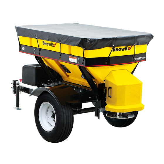
- Page 1 Assembly Instructions SP-7000 Serial No. 140410300001SP-7000 and higher CUSTOMER COPY Madison Heights, Michigan 48071 800-SALTERS www.snowexproducts.com © TrynEx International 2014 F51558 REV-A140905...
-
Page 2: Trynex International 2014 F51558 Rev-A140905
Introduction These Installation Instructions have been designed to guide you while assembling and installing your SnowEx spreader. Follow these instruc- tions with care to ensure performance and longevity. Please read and understand the safety warnings associated with the assembly and installation of the spreader before beginning. In addition the safety information in the these instructions, observe general safety guidelines to maintain your safety and the safety of those around you. - Page 3 Assembly Instructions STEP 1 Unpack the spreader; remove the axle, tires, tongue, and spinner drive from the pallet, set aside so the main spreader assembly is alone on the pallet. STEP 2 Open the Spinner Drive Box. Open and locate the hardware kits. AXLE WHEELS TONGUE...
- Page 4 Assembly Instructions STEP 4 Lift the spreader and support it to allow installation of the axle and trailer tongue. Once lifted, remove and discard the pallet. As a safeguard, in addition to the support jacks underneath the spreader, leave the lifting device in place. STEP 5 Fasten the Axle to the frame.
- Page 5 Assembly Instructions STEP 9 Lower the tongue jack; pin in the vertical position. Remove the supports. Lower the spreader to rest on the tongue jack and the wheels. STEP 10 Mount the fenders over the wheels. STEP 11 Attach the ‘mud flap’ to the rear of the fenders. Use the clamp plate on the outside of the mud flap. STEP 12 Attach the spinner drive: lower the drive onto the pegs at the rear of the frame;...
-
Page 6: Step
Assembly Instructions STEP 13 Install and connect batteries (under cover). Batteries are not included with the spreader. Use the long wires from T30725 to connect the batteries to each other. Use the short wires to connect to the control board: Red to “BAT +” and Black to “GROUND”. Install the cover when finished. -
Page 7: Step
Vehicle Wiring Instructions STEP 1 Determine the location of the vehicle’s battery. STEP 2 Mount the breaker within 12 inches of the battery’s positive terminal. STEP 3 Route the harness from the rear of the vehicle, near the drawbar, to the battery. Leave enough harness free near the hitch to allow connect- ing to the trailer tongue plug. -
Page 8: Step
Notes © TrynEx International 2014 F51558 REV-A140905... -
Page 9: Step
Notes © TrynEx International 2014 F51558 REV-A140905... - Page 10 Notes © TrynEx International 2014 F51558 REV-A140905...
- Page 11 Notes © TrynEx International 2014 F51558 REV-A140905...
- Page 12 140905...
Need help?
Do you have a question about the SP-7000 and is the answer not in the manual?
Questions and answers