Table of Contents
Advertisement
Installation Instructions
Model ZIC-4A
Zone Indicating Card
P/N 315-033050-15
Siemens
Siemens
Industry
Industry, , , , , Inc.
Industry
Siemens
Siemens Industry
Siemens
Industry
Building T T T T T ec
Building
Building
ec
ec
hnologies Di
hnologies Di
Building
Building
echnologies Di
ec
hnologies Division
hnologies Di
Inc.
Inc.
Inc.
Inc.
vision
vision
vision
vision
Advertisement
Table of Contents

Related Manuals for Siemens ZIC-4A


Summary of Contents for Siemens ZIC-4A
- Page 1 Installation Instructions Model ZIC-4A Zone Indicating Card Siemens Siemens Industry Industry, , , , , Inc. Industry Inc. Inc. Siemens Siemens Siemens Industry Industry Inc. Inc. Building Building Building T T T T T ec hnologies Di hnologies Di vision...
-
Page 2: Table Of Contents
ZIC-4A Supervised Municipal Tie Wiring ............13 ZIC-4A Leased Line Wiring ................13 ZIC-4A Releasing Service Wiring ..............14 ZIC-4A Releasing Service Wiring With PSC-12 Power Supply ......15 ZIC-4A Bell Follower Circuit Wiring ..............16 ZIC-4A Two-Channel Audio Wiring..............17 ZIC-4A Single-Channel Audio Wiring ............... -
Page 3: Introduction
Fire Safety Modular), FCM2041-U3 (Cerberus PRO Modular). During the initial power-up condition, each zone on the ZIC-4A is configured as a steady NAC, Class A configuration with 2A current limit. The ZIC-4A then sends a message to the PMI/PMI-2/PMI-3 (XLS),... -
Page 4: Operation
OPERATION The ZIC-4A contains four Class A circuits. Each circuit is rated at 3A at 24VDC and has an input connected to the power source and an output where the NAC devices, Municipal Tie, Releasing service and Leased Line remote monitoring device are connected. -
Page 5: Pre-Installation
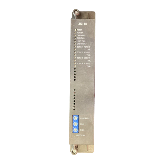
TROUBLE (Yellow) Normally OFF . When illuminated, indi- cates that the ZIC-4A has detected a trouble on Zone 2 (open circuit or short circuit). ZONE 3 ACTIVE (Red) Normally OFF . When illuminated, indi- cates that Zone 3 is active. -
Page 6: Output Zones
(Refer to Figure 1 for the location of the switches.) The address for the ZIC-4A must be the same as the address selected for it in the Zeus Programming Tool. To set the address, turn the pointers on each of the three dials to the numbers for the selected address. -
Page 7: Zic-4A Switch And Jumper Settings
Each ZIC-4A card is subdivided into four output circuits that can be programmed independently of each other. In the Zeus Programming Tool, highlight the selected ZIC-4A Output Ckt in the Physical View and open the Detail View - Properties to modify and/or define the following ZIC-4A output circuit properties: Device Address Shows preset address of ZIC card output. -
Page 8: Wiring
Remove all system power before installation, first battery then AC. (To power up, connect the AC first, then the battery.) All field wiring to the ZIC-4A is connected to OUTPUTS SHOWN IN ACTIVE STATE the terminal blocks of the CC-5 card cage... -
Page 9: Using Multiple Power Supplies
The screw terminals can accommodate one 12-18 AWG or two 16-18 AWG. If the total output of all 4 zones exceeds 12 amps, a single PSC-12 cannot be used to supply the ZIC-4A. Refer to the PSC-12 Installation Instructions, P/N 315-033060 for information when the total system load exceeds 12 amps. -
Page 10: Installation
The ZIC-4A plugs perpendicularly into one slot in the CC-5 card-cage via two 96-pin DIN connectors and can occupy any slot in the card cage. (Refer to Figure 5.) Insert the ZIC-4A card into the card guides right side up (lettering on the front panel is legible). -
Page 11: Configurations
To calculate the maximum current, the following equation should be used: ZIC-4A Total Current = ZIC-4A Standby Current + [Zone 1 Usage Req. (See Table above) + Class A current (if Class A)] + [Zone 2 Usage Req. (See Table above) + Class A current (if Class A)] + [Zone 3 Usage Req. -
Page 12: Zic-4A Supervised Notification Appliance Wiring
(CLASS A) ZONE 4 CLASS B ZONE 3 24K, 24K, ONE SLOT OF CC-5 ZONE 1 ZONE 2 ZONE 3 ZONE 4 INPUT INPUT INPUT INPUT Figure 6 ZIC-4A Supervised Notification Appliance Wiring Siemens Industry, Inc. P/N 315-033050-15 Building Technologies Division... -
Page 13: Zic-4A Supervised Municipal Tie Wiring
Siemens Industry, Inc. P/N 315-033050-15 Building Technologies Division... -
Page 14: Zic-4A Releasing Service Wiring
ZIC-4A Releasing Service Wiring series.) 17 . Wiring diagram shown for 6VDC solenoids (4 units in series.) 18. The ZIC-4A circuit must be configured as “NAC Steady” . The “Releasing Zone” usage in Zeus is only to be used for legacy UL releasing... -
Page 15: Zic-4A Releasing Service Wiring With Psc-12 Power Supply
Both interlocks must be open at the same time to allow for the flow of water to initiate. A specific sequence of operation is required with all Siemens panels with listed releasing capabilities. The FireFinder-XLS/Desigo Fire Safety Modular/Cerberus PRO Modular panel will indicate an alarm if one detector detects an alarm condition. -
Page 16: Zic-4A Bell Follower Circuit Wiring
ONE SLOT OF CC-5 BELL FOLLOWER PRIMARY INPUT FIRE ALARM PANEL BELL EXTENDER TO PSC-12, TB4 - NAC OUTPUT SHOWN IN ACTIVE STATE TO PSC-12, TB4 + Figure 11 ZIC-4A Bell Follower Circuit Wiring Siemens Industry, Inc. P/N 315-033050-15 Building Technologies Division... -
Page 17: Zic-4A Two-Channel Audio Wiring
ZONE 4 (CLASS B) 24K, 24K, ONE SLOT OF CC-5 AUDIO FROM PREVIOUS CHANNEL A ZIC-4A OR FROM ZAC-40/ TO NEXT ZAM-180 TERMINALS ZIC-4A CHANNEL B 1A AND 1B OR 2A AND 2B NOTES 1. All wiring must be in accordance with Article 760 of NEC or local building codes. Wiring for each zone can either be Class A or Class B. -
Page 18: Zic-4A Single-Channel Audio Wiring
(CLASS B) 24K, 24K, ONE SLOT OF CC-5 AUDIO FROM PREVIOUS TO NEXT ZIC-4A ZIC-4A OR FROM ZAC-40/ ZAM-180 TERMINALS 1A AND 1B OR 2A AND 2B Figure 13 ZIC-4A Single-Channel Audio Wiring Siemens Industry, Inc. P/N 315-033050-15 Building Technologies Division... -
Page 19: Zic-4A Two-Channel Audio And Strobe Wiring
NAC current draw. (See Table) 11. Zone Usage pair is interchangeable. Verify proper wiring. 12. Positive or negative ground fault detected at <40K ohms for terminals 1-16. Figure 14 ZIC-4A Two-Channel Audio And Strobe Wiring Siemens Industry, Inc. P/N 315-033050-15 Building Technologies Division... -
Page 20: Zic-4A Single-Channel Audio And Strobe Wiring
NAC current draw. (See Table) 11. Zone usage pair is interchangeable. Verify proper wiring. 12. Positive or negative ground fault detected at 40K ohms for terminals 1-16. Figure 15 ZIC-4A Single-Channel Audio And Strobe Wiring Siemens Industry, Inc. P/N 315-033050-15 Building Technologies Division... - Page 21 Siemens Industry, Inc. P/N 315-033050-15 Building Technologies Division...
- Page 22 Cyber security disclaimer Siemens products and solutions provide security functions to ensure the secure operation of building comfort, fire safety, security management and physical security systems. The security functions on these products and solutions are important components of a comprehensive security concept.
- Page 23 This page has been left intentionally blank. Siemens Industry, Inc. P/N 315-033050-15 Building Technologies Division...
- Page 24 This page has been left intentionally blank. For CE applications in Cerberus E100 systems refer to Installation Instruction A24205-A334-B844 (English) or A24205-A334-A844 (German). Siemens Industry, Inc. Siemens Canada, Ltd. Siemens Gebäudesicherheit P/N 315-033050-15 Building Technologies Division 1577 North Service Road East GmbH &...
Need help?
Do you have a question about the ZIC-4A and is the answer not in the manual?
Questions and answers