Table of Contents
Advertisement
Advertisement
Chapters
Table of Contents

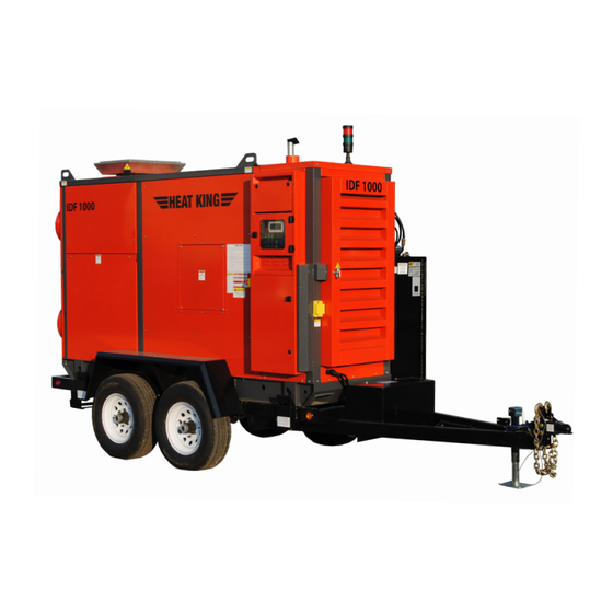
Summary of Contents for Heat King IDF1000
- Page 1 Part #460468 Rev #001 IDF1000 Operation Manual...
- Page 2 As a new customer of Heat King we would like to welcome you! We are looking forward to providing you with technical support for your Heat King unit. Whatever you need we are here to help. Ways to contact us for support...
- Page 3 WARNING CALIFORNIA - Proposition 65 Warning Engine exhaust and some of its constituents and some dust created by power sanding, sawing, grinding, drilling and other construction activities contains chemicals known to the State of California to cause cancer, birth defects and other reproductive harm.
-
Page 4: Table Of Contents
Table of contents Section Title Pages Warning Safety Introduction Training sign off Warranty 12-13 How it works 14-15 Controls 16-20 Operating procedures Maintenance 22-29 Service parts Troubleshooting 31-34 Lifting instructions Specifications MSDS 37-40 Schematics 41-44... - Page 5 The Safety Alert symbol identifies ATTENTION! BECOME ALERT! important safety messages on the YOUR SAFETY IS INVOLVED! Tamarack Heat King and in the manual. When you see this symbol, be alert to the possibility of personal injury or death. Follow the instruc- tions in the safety message.
- Page 6 Heater. the Heat King be familiar with the operating and maintenance procedures and related SAFETY Only trained competent persons shall operate information contained in this manual. This manual the Heater.
- Page 7 TIRE SAFETY 11. Hot surface ~ Avoid contact with hot exhaust and glycol system. Allow to cool before performing repairs 1. Failure to follow proper procedures when or service. mounting a tire on a wheel or rim can produce an explosion which may result in serious injury or death.
- Page 8 INSTALLATION SAFETY 1. Use only fuel for the heater burner specified in the burner section of model specifications. The use of in- correct fuel may result in fire or explosion and sever injury to the operator. 2. Fuel burning equipment must have proper ventilation for cooling, combustion air, and exhausting of combustion BEFORE INSTALLATION products...
- Page 9 OPERATING SAFETY MAINTENANCE SAFETY 1. Review the Operator's Manual and all safety 1. Read and understand the Operator’s Manual items before working with, maintaining or and all safety signs before operating, servic- operating the Heater. ing, maintaining or adjusting the Heater. 2.
-
Page 10: Warning
7. Raise and secure the hitch jack. * Read the Operator's Manual before towing. 8. Reverse the Heat King set-up procedure t 9. Check and be sure that all lights are working. 10. Do not allow riders on machine. 11. Never exceed a safe travel speed. - Page 11 STORAGE SAFETY 1. Store unit in an area away from human activity. 2. Do not permit children to play on or around the stored Heater. PLACING IN STORAGE 7. Move to storage area. 8. Select an area that is dry, level and free of de- After the season's use, the machine should be thor- bris.
-
Page 12: Introduction
This equipment has been designed and manufactured to meet the needs of the buyer for the efficient heating of construction sites. Safe, efficient and trouble free operation of your IDF1000 requires that you and anyone else who will be oper- ating or maintaining the Heater, read and understand the Safety, Operation, Maintenance and Trouble Shoot- ing information contained in the Operator's Manual. - Page 13 Tamarack Industries follows the general Safety Standards specified by the Society of Automotive Engi- neers (SAE) and the Occupational Safety and Health Administration (OSHA). Anyone who will be operat- ing and/or maintaining the Heat King must read and clearly understand ALL Safety, Operating and Mainte- nance information presented in this manual.
-
Page 14: Warranty
Distributor Name Address Address City, State, Code City, State, Code Phone Number ( Check One: Contact Name Private Heat King Model Contractor Serial Number Other Delivery Date DISTRIBUTOR INSPECTION REPORT SAFETY Tire Pressure Checked Emergency Stop Switch Works Wheel Bolts Torqued... -
Page 15: Warranty
Tamarack Industries CONDITIONS OF SALES & LIMITED WARRANTY All sales made by Tamarack Industries, here after ref- from contract, or the performance or breach thereof, or ered to as Tamarack, a Division of ELJO Industries Inc. the design, manufacture, sale, delivery, resale, installa- are subject to these conditions unless otherwise agreed tion, technical direction of installation, inspection, repair, in writing with a duly authorized officer of Tamarack. -
Page 16: How It Works
How It Works TRAILER High Temp Heat Exchanger Building Circulating Fan Burner Construction site Engine Temp Oil supply Diesel Engine Low pressure Oil Engine STAND ALONE UNIT OPTIONAL FUEL TANK ON TRAILER Diesel Tank 123 USGal HOW THE MACHINE WORKS Indirect fired: This equipment was designed for space heating of buildings under construction, as an outdoor application with flue gases discharged outdoors. - Page 17 Protective devices The IDF1000 is equipped with the following protective devices to protect the user: E-STOP The emergency stop switch is monitored by the controller inputs. The input is connected to ground when the switch is pressed. In the event of an e-stop condition the system mode is set to OFF and all output functions are shut down by the controller.
-
Page 18: Controls
Controls... -
Page 23: Operating Procedures
Operating Procedures BEFORE STARTING THE UNIT * Ensure there is at least 2 feet (0.7 Meters) of clearance around machine. * If outdoor temperature is below 14°F or -10°C plug in the engine heater for 2-3 hours before starting. It requires a 120 VAC / 60 hz power supply. * Verify engine oil level. -
Page 24: Maintenance
Maintenance On the IDF1000 there are 4 areas of maintenance. 1. Engine 2. Burner 3. Blower belt 4. Heat Exchanger Engine SECTION 6... - Page 25 Engine maintenance chart Daily and periodic maintenance is important to keep the engine in good operating condition. The fol- lowing is a summary of maintenance items by periodic intervals. Periodic maintenance intervals vary depending on application, loads and operating conditions. The following should be treated as a gen- eral guideline.
- Page 26 Changing the engine oil To avoid personal injury: 5. Add new oil to the engine through either Be sure to stop the engine before draining of the oil filler ports (#1) engine oil. When draining engine oil, place some container underneath the engine and dis- pose it according to local regulations.
- Page 27 Fuel filter and water separator Replace the fuel filter at specified intervals Drain the fuel/Water separator whenever to prevent contaminants from adversely af- there are contaminants such as water col- fecting the diesel fuel flow. lected in the bottom of the cup. Never wait until the scheduled periodic maintenance if 1.
- Page 28 Air filter The engine performance is adversely affected when the air cleaner element is clogged with dust. Be sure to clean the air filter element periodically. NOTICE: When the engine is operated in dusty conditions clean the air filter element more frequently.
- Page 29 Heat King model. NOTE: use semi solid or hollow cone spray pattern nozzels. IDF1000 use a 5.5 GPH, 80° nozzle @ 125 psi NOTE : FOR HIGH ALTITUDE USE (4000+ ft above sea level). Use the appropriate size for your heat king model.
- Page 30 Blower Belt Belt Replacement Replacing the blower drive belts: Tools required: Phillips driver, 3/4” wrench (replacement belt part # 460693) • Remove 2 inspection doors on the right side of the unit using a Phillips drive. • Using a ¾” wrench, push down on the tensioner pulley to remove tension from the belts •...
- Page 31 Heat Exchanger Heat Exchanger Cleanouts Inspect Heat Exchanger annually and clean as necessary using cleanout brushes and heat exchanger cleaning chemicals. Cleaning the Heat Exchanger Tools Required: 3/8” wrench, 7/16” wrench, 5/8” wrench, shop vac, cleanout brushes, chemicals as required. •...
-
Page 32: Service Parts
Service Parts Item Part # Burner 5.5 GPH 80°A Nozzle 460708 Left Electrode 461055 Right Electrode 461055 Cad cell 461057 Transformer 461053 Gap Guage Tool 461017 Primary Control 461056 Fuel Filter 445157 Burner Gasket 460408 Engine Oil Filter 461555 Fuel Filter Element 461556 Air Filter 461557... - Page 33 TROUBLESHOOTING Engine Troubleshooting TROUBLESHOOTING If the engine does not function properly, use the following chart to identify and correct the cause. B When it is difficult to start the engine B When engine suddenly stops Countermeasures Cause Countermeasures Cause Check the fuel tank and refill the fuel, if Check the fuel tank and fuel filter.
-
Page 34: Troubleshooting
Troubleshooting The Tamarack Construction Heat King IDF1000 is a self-contained heating system that can be used maintain a work area at a constant temperature. It is a simple system that requires minimal maintenance. In the following trouble shooting section, we have listed many of the problems, causes and solutions to the problems which you may encounter. - Page 35 Alarms When an active alarm is present, the [Alarm] key will flash red. Pressing the key will take the operator to the main alarm screen:...
- Page 36 ALARM RESET Alarms can be reset by the operator through the alarm screen. This is done by pressing and holding the [Alarm] for 3 seconds: ALARM LOGGER The alarm logger contains a list of historical alarm events for the purpose of troubleshooting. The log- ger can be accessed through the alarm screen by pressing the [Enter] key: The records can be scrolled through using the up and down keys.
-
Page 37: Lifting Instructions
Lifting Instructions The IDF1000 can be lifted by forklift with the forklift pockets located on either side of trailer tires or with the optional lifting frame. SECTION 9... -
Page 38: Specifications
IDF1000 Specifications General Capacities and Component Specifications Height (w/ heater vent) 77 in. Width 55 in. Length 129 in.. Weight 3360 lbs. Engine Yanmar Tier 4 diesel Burner Wayne MSR-DC Clutch Centrifugal 1600 rpm engagement Optional Trailer With Fuel tank Height (W/heater vent) 96 in. - Page 39 Material Safety Data Sheet WHMIS (Pictograms) WHMIS (Classification) Protective Clothing TDG (pictograms) B-3, D-2B Section 1. Chemical Product and Company Identification DIESEL FUEL W104 Product Name Code SAP: 120, 121, 122, 287 Validated on 3/2/2001. Diesel 50, Diesel 50 LS, #1 Diesel , #1 Diesel LS, Diesel LC, Seasonal Diesel, Synonym Seasonal Diesel LS, Diesel AA, Domestic Marine Diesel, International marine Diesel, Seasonal Diesel Locomotive, Domestic Marine diesel LS, diesel -20°C...
- Page 40 DIESEL FUEL Page Number: 2 Fire Fighting NAERG96, GUIDE 128, Flammable liquids (Non-polar/Water-immiscible). CAUTION: This product has a moderate flash point above 40ºC: Use of water spray when fighting fire may be inefficient. Media and Instructions If tank, rail car or tank truck is involved in a fire, ISOLATE for 800 meters (1/2 mile) in all directions; also consider initial evacuation for 800 meters (1/2 mile) in all directions.
- Page 41 DIESEL FUEL Page Number: 3 Vapour Pressure 1.0 kPa @ 20ºC (7.5 mmHg @ 68ºF). Dispersion Properties Not available Volatility <0.1 (Butyl acetate = 1), less than gasoline. Solubility Insoluble in cold water, soluble in non-polar hydrocarbon solvents. Section 10. Stability and Reactivity Not available Corrosivity Stability...
-
Page 42: Msds
DIESEL FUEL Page Number: 4 Section 13. Disposal Considerations Preferred waste management priorities are: (1) recycle or reprocess; (2) incineration with energy recovery; (3) disposal at Waste Disposal licensed waste disposal facility. Ensure that disposal or reprocessing is in compliance with government requirements and local disposal regulations. -
Page 43: Schematics
Schematics Schema�c Legend H6-12VCOM-BLK-6 Symbol Device ID Descrip�on FS-x Fuse SW-x Switch TB-x PLC Terminal NO Relay Contact Relay Coil Solenoid Heater Ba�ery BAT-x Light TSH-x High Temp SW TSL-x Low Temp SW PSL-x Low Pressure SW PSH-x High Pressure SW H5-12VCOM-BLK-14 E-Stop ES-x... -
Page 44: H6-12Vcom-Blk-6
BAT-1 Ba�ery Disconnect H6-12VDC-RED-6 H6-12VCOM-BLK-6 Symbol Alternator S F L P H2-ALT1-BLK-14 Alternator Status (A1) (A2) Fuel Pump 12VDC-RED-10 H2-I1-RED-10 (30) (87) Fuel Solenoid BLACK FS-2 Starter Solenoid H2-S1-RED-10 (30) (87) Fuel Solenoid WHITE BLACK Pre-Heat Glow Plugs FS-3 H2-HTR1-RED-10 (30) (87) Stack Light... -
Page 45: Fs-X
From Electrical E1 From Electrical E1 Schem 12VDC 12VCOM LED1 (System Power) Symbol FS-x (11) (14) SW-1 PS-1 SW-x H1-12VDC-RED-14 H1-12VCOM-RED-14 TB-x System Off Req c.pCOe FS-1 c.pCO H1-SW1-BLK-14 24VCOM-GRY-14 c.pCOe ES-1 BAT- 24VCOM-GRY-14 c.pCO C1/2 Starter 24VCOM-GRY-18 TSL- (85) (86) Igni�on 24VCOM-GRY-18... -
Page 46: Schema�C Legend
ES1_2-ORG-16 Tachometer NO Relay Contact (BRN) (BLK) IN_COM-GRY-16 (BLU) H2-TACH1-GRY-16 Relay Coil c.pCO Engine Low Oil Pressure IN_COM-GRY-16 PSL1 H2-PSL1-GRY-16 Solenoid Schema�c Legend Air Out PT1000 TT1-BLU H3-TT1 Engine Low Oil Pressure Symbol Device ID Descrip�on Heater TSH1 Engine Over Temp IN_COM-GRY-16 H2-TSH1-GRY-16 TT1-WHT... - Page 47 1205 SHERWIN RD WINNIPEG, MANITOBA CANADA R3H 0V3 WWW.HEAT-KING.CA Support@tamarack-ind.com 1-8800-661-0304 1-204-885-7557 HEATKINGTECH...
Need help?
Do you have a question about the IDF1000 and is the answer not in the manual?
Questions and answers