Table of Contents
Advertisement
Available languages
Available languages
Quick Links
NATURAL GAS MODELS:
PROPANE GAS MODELS:
SAFETY INFORMATION
WARNING
!
FIRE OR EXPLOSION HAZARD
Failure to follow safety warnings exactly
could result in serious injury, death, or
property damage.
- Do not store or use gasoline or other
fl ammable vapors and liquids in the vicinity of
this or any other appliance.
- WHAT TO DO IF YOU SMELL GAS:
•
Do not try to light any appliance.
•
Do not touch any electrical switch; do not
use any phone in your building.
•
Immediately call your gas supplier from a
neighbour's phone. Follow the gas
supplier's instructions.
•
If you cannot reach your gas supplier, call
the fi re department.
- Installation and service must be
performed by a qualifi ed installer, service
agency, or the supplier.
This appliance may be installed in an aftermarket,
permanently located, manufactured home (USA
only) or mobile home, where not prohibited by
local codes.
This appliance is only for use with the type of gas
indicated on the rating plate. This appliance is
not convertible for use with other gases, unless
a certifi ed kit is used.
INSTALLER:
Leave this manual with the appliance
CONSUMER:
Retain this manual for future reference
Wolf Steel Ltd., 24 Napoleon Rd., Barrie, ON, L4M 0G8 Canada / 103 Miller Drive, Crittenden, Kentucky, USA, 41030
Phone 1 (866) 820-8686 • www.napoleonfi replaces.com • hearth@napoleonproducts.com
$10.00
BHD4PN / BHD4STN / BHD4PGN / BHD4STGN / BHD4PFCN / BHD4STFCN
ADD PRODUCT CODE HERE (TRADE GOTHIC LT STD FONT)
BHD4PP / BHD4STP / BHD4PGP / BHD4STGP / BHD4PFCP / BHD4STFCP
INSTALLATION AND
ADD MANUAL TITLE
OPERATION MANUAL
CERTIFIED TO THE CANADIAN AND AMERICAN NATIONAL STANDARDS:
CSA 2.22 AND ANSI Z21.50 FOR VENTED DECORATIVE GAS APPLIANCES
IF INSTALLATION + OPERATION, ADD SERIAL
CSA /
INTERTEK
BARCODE LABEL ON THE OWNER'S MANUAL"
LOGO
Product Name / Code
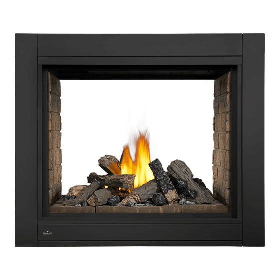
Ascent™ Multi-View
ADD ____ ILLUSTRATED
ADD PRODUCT IMAGE
FOR INDOOR USE ONLY
NUMBER LABEL HERE
IF SEPARATE MANUALS, ADD "PLACE
ENGLISH
FRENCH PG. 69
(see price book)
(BHD4ST illustrated)
W415-1285 / G / 04.27.18
Advertisement
Chapters
Table of Contents

Related Manuals for Napoleon Ascent BHD4PN


Summary of Contents for Napoleon Ascent BHD4PN
- Page 1 INTERTEK BARCODE LABEL ON THE OWNER’S MANUAL” LOGO Wolf Steel Ltd., 24 Napoleon Rd., Barrie, ON, L4M 0G8 Canada / 103 Miller Drive, Crittenden, Kentucky, USA, 41030 Phone 1 (866) 820-8686 • www.napoleonfi replaces.com • hearth@napoleonproducts.com $10.00 W415-1285 / G / 04.27.18...
- Page 2 safety information WARNING DANGER • This appliance is hot when operated and can cause severe burns if contacted. • Any changes or alterations to this appliance or its controls can be dangerous and is prohibited. HOT GLASS WILL CAUSE • Do not operate appliance before reading and BURNS.
- Page 3 free from combustible materials, gasoline and other fl ammable vapors and liquids. • If the appliance shuts off, do not re-light until you provide fresh air. If appliance keeps shutting off, have it serviced. Keep burner and control compartment clean. •...
-
Page 4: Table Of Contents
table of contents general information 10.0 finishing rating plate / lighting instruction 10.1 shipping bracket location 10.2 main safety barrier removal / mobile home installation installation 10.3 end safety barrier removal / installation dimensions (BHD4P only) venting requirements 10.4 main door removal / installation typical vent installations 10.5 end door removal / installation (BHD4P... - Page 5 standard checklist Installer: please fill out the following information Customer: Address: Date of Installation: Location of appliance: Installer: Dealer/Distributor contact number: Serial #: Model: BHD4PN BHD4STN BHD4PP BHD4STP Natural Gas: Propane: BHD4PGN BHD4STGN BHD4PGP BHD4STGP BHD4PFCN BHD4STFCN BHD4PFCP BHD4STFCP Fuel Type Natural Gas Propane Altitude (FT)
-
Page 6: General Information
general information 1.0 general information When the appliance is installed at elevations above 4,500ft (1372m), and in the absence of specific recommendations from the local authority having jurisdiction, the certified high altitude input rating shall be reduced at the rate of 4% for each additional 1,000ft (305m). - Page 7 general information WARNING • Always light the pilot whether for the first time or if the gas supply has run out, with the glass door opened or removed. • Provide adequate clearance for servicing and operating the appliance. • Provide adequate ventilation. •...
-
Page 8: Rating Plate / Lighting Instruction Location
ELECTRICAL RATING: 115V.60HZ. LESS THAN 12 AMPERES SPÉCIFICATIONS ÉLECTRIQUES : 115 V, WOLF STEEL LTD. SERIAL NUMBER/ NO. DE SÉRIE: BHD4 24 NAPOLEON ROAD, BARRIE, ON, L4M 0G8 CANADA 60HZ. MOINS DE 12 AMPÈRES. W385-1936 / A MAX SIZE: 8 1/2” X 4 3/4”... -
Page 9: Dimensions
general information 2.0 dimensions 25 1/8" 638mm 8" 203mm 5" 12 13/16" 325mm 127mm RIGHT LEFT 34 3/16" SIDE SIDE SAFETY BARRIER 868mm 38 1/4" 841mm 2 1/16" 53mm 7 9/16" 43 1/4" 1099mm 192mm 7 9/16" GAS INLET 192mm BHD4P ILLUSTRATED ELECTRICAL INLET 8"... -
Page 10: Venting Requirements
venting requirements 3.0 venting requirements WARNING WARNING • Risk of fi re. Maintain specifi ed air space clearances to vent pipe and appliance. • The vent system must be supported every 3’(0.9m) for both vertical and horizontal runs. Use support ring assembly W010-0067 or equivalent non-combustible strapping to maintain the minimum clearance to •... - Page 11 This template must be used in conjunction with templates 7.2.1 or 7.2.2, depending on termina- tion shape (i.e. round, or round and square). See appropriate templates folder. venting requirements For optimum fl ame appearance and appliance performance, keep the vent length and number of elbows to a minimum.
-
Page 12: Typical Vent Installations
venting requirements typical vent installations 16" MIN (40.6cm) 40 FT (12m) 36" (91.4cm) 24" (61cm) 38 1/4" 43" (109.2cm) (97.2cm) MIN PLUS RISE* When venting, the horizontal run must be kept to a When terminating vertically, the vertical rise is a maximum of 20 feet (6m). -
Page 13: Special Vent Installations
venting requirements special vent installations 3.2.1 periscope termination Use the periscope kit to locate the air termination above grade. The periscope must be installed so that when fi nal grading is completed, the bottom air slot is located a 12" minimum of 12”... -
Page 14: Converting From 5/8" To 4/7" Venting
venting requirements converting from 5/8" to 4/7" venting Use Mill Pac to seal adapter to the appliance collars. Ue Mill Pac to seal adapter to the appliance collars. Use red RTV silicone sealant to seal adapter to the appliance collars. note: Depending on your adaptor kit, the 4/7"... -
Page 15: Vent Terminal Clearances
venting requirements vent terminal clearances Covered balcony applications ††* = 3 feet ≤ 15 feet = 2 x ACTUAL (0.9m) (4.6m) note: INSTALLATIONS Wall terminals are for illustration purposes only. Size and shapes may vary. CANADA U.S.A. 12” (30.5cm) 12” (30.5cm) Clearance above grade, veranda porch, deck or balcony. -
Page 16: Vent Application Flow Chart
venting requirements vent application flow chart Top Exit Horizontal Termination Vertical Termination Vertical rise is equal Vertical rise is equal Vertical rise is less Vertical rise is less to or greater than the to or greater than the than horizontal run than horizontal run horizontal run horizontal run... -
Page 17: Horizontal Termination
venting requirements horizontal termination ) < (V See graph to determine the required vertical rise V for the required Simple venting configuration (only one 45° and 90° elbow) horizontal run H 39 (11.9) REQUIRED 30 (9.1) VERTICAL RISE IN FEET 20 (6.1) (METERS) V 10 (3.1) - Page 18 venting requirements ) > (V Simple venting configuration (only one See graph to determine the required vertical rise V for the 45° and 90° elbow) required horizontal run H 12.3 (3.8) REQUIRED 8.3 (2.5) VERTICAL RISE IN FEET (METERS)V 4.8 (1.5) 4.2 (1.3) (1.5) (3.1)
-
Page 19: Vertical Termination
venting requirements vertical termination ) < (V Simple venting configurations. See graph to determine the required vertical rise V for the required horizontal run H 40 (12.2) 30 (9.1) REQUIRED VERTICAL RISE 20 (6.1) IN FEET (METERS) V 10 (3.1) 3 (0.9) 10 (3.1) (1.5) - Page 20 venting requirements ) > (V Simple venting configurations. See graph to determine the required vertical rise V for the required horizontal run H 20 (6.1) 19 (5.8) REQUIRED VERTICAL RISE IN FEET 10 (3.1) (METERS) V 3 (0.9) (1.5) (3.1) (4.6) (6.1) (7.6)
-
Page 21: Framing
framing 4.0 framing note: When using optional fi nishing accessories, the framing dimensions and fi nishing materials may differ from what is outlined in the section below; refer to the leafl et instructions supplied in the accessory kit for specifi c framing and fi nishing specifi cations. -
Page 22: Framing
framing framing 4.1.1 see-thru framing (BHD4ST) A: MIN 22 1/8" (56.2cm) 46 1/2" MAX 24 1/8" (61.3cm) [118cm] 45 1/2" [115.6cm] 4.1.2 peninsula framing (BHD4P) A: MIN 22 1/8" (56.2cm) MAX 24 1/8" (61.3cm) B: MIN 42 1/2" (108cm) MAX 43 1/2" (110.5cm) note: All framing dimensions are based on the finishing material supports position. -
Page 23: Minimum Clearance To Combustible Enclosures
framing minimum clearance to combustible enclosures IMPORTANT: This appliance requires a minimum inside enclosure height of 50" (127cm), measured from the bot- tom of the appliance. For temperature requirements, this area must be left unobstructed. note: This appliance is not load bearing. Combustible IMPORTANT: The firestop assembly provided must be used when the vent pipes pass through any walls or are terminated horizontally. -
Page 24: Venting Installation
5.0 venting installation venting installation WARNING • Ensure to unpack all loose materials from inside the fi rebox prior to connecting the gas and electrical supply • If your appliance is supplied with a remote, ensure the remote receiver is in the “OFF” position prior to connecting the gas and electrical supply to the appliance. -
Page 25: Horizontal Installation
venting installation horizontal installation WARNING • The fi restop assembly must be installed with the vent shield to the top. • Terminals must not be recessed into a wall or siding more than the depth of the return fl ange of the mounting plate. -
Page 26: Using Flexible Vent Components
venting installation using flexible vent components WARNING • Do not allow the inner fl ex pipe to bunch up on horizontal or vertical runs and elbows. Keep it pulled tight. • Spacers are attached to the inner fl ex pipe at predetermined intervals to maintain an even air gap to the outer fl ex pipe. -
Page 27: Horizontal Air Terminal Installation
Outer Flex Pipe 2" (50.8mm) Overlap venting installation Red RTV Silicone Screws (Supplied) 5.3.1 horizontal air terminal installation Stretch the inner fl ex pipe to the required length taking ADD FASTENER TYPE into account the additional length needed for the fi nished Screws Red RTV Silicone wall surface. -
Page 28: Vertical Air Terminal Installation
venting installation 5.3.2 vertical air terminal installation WARNING • Maintain a minimum 2” (51mm) space between the air inlet base and the storm collar. note: Fastening hardware provided with appropriate roof terminal and liner kits. Fasten the roof support to the roof using 6 screws. The roof support is optional. -
Page 29: Electrical Information
6.0 electrical information electrical information hard wiring connection It is necessary to hard wire this appliance. Permanently framing the appliance with an enclosure, requires the appliance junction box to be hard wired. This appliance must be electrically connected and grounded in accordance with local codes. In the absence of local codes, use the current CSA C22.1 Canadian electrical code in Canada or the ANSI/NFPA national electrical code in the United States. -
Page 30: Battery Back-Up Installation
electrical information battery back-up installation note: In the event of a power failure, your appliance can be operated using the supplied battery back-up. A. Remove the safety screen and door, refer to the "main safety barrier removal / installation" and "main door removal / installation"... -
Page 31: Wiring Diagram
electrical information wiring diagram WARNING • Do not wire 110 volts to the valve or wall switch. ACS/IPI SWITCH (OPTIONAL) GREEN ON / OFF ORANGE SWITCH TRANSFORMER IPI / CPI ON / OFF BATTERY HOUSING ELECTRONIC DISCONNECT THESE VALVE CONNECTIONS TO THE ON/OFF SWITCH. -
Page 32: Gas Installation
7.0 gas installation gas installation WARNING • Risk of fi re, explosion, or asphyxiation. Ensure there are no ignition sources such as sparks or open fl ames. • Support gas control when attaching gas supply pipe to prevent damaging gas line. •... -
Page 33: Nailing Tab Installation
8.0 nailing tab installation nailing tab installation Nailing tabs are provided as part of the frames, as shown. To determine the final location and where to bend the nailing tabs you must first determine the thickness of your finishing material (i.e. NAILING IMAGE drywall). -
Page 34: Operating Instructions
9.0 operating instructions nailing tab installation When lit for the first time, the appliance will emit a slight odour for a few hours. This is a normal temporary condition caused by the “burn-in” of internal paints and lubricants used in the manufacturing process and will not occur again. -
Page 35: Finishing
10.0 finishing finishing WARNING • Risk of fire! • Never obstruct the front opening of the appliance. • The front of the appliance must be finished with any non-combustible materials such as brick, marble, granite, etc., provided that these materials do not go below the specified dimension, as illustrated. •... -
Page 36: End Safety Barrier Removal / Installation (Bhd4P Only)
finishing 10.3 end safety barrier removal / installation (BHD4P only) note: One of the main safety barriers must be removed prior to end barrier removal, see "main safety barrier removal / installation" section. Remove the 4 securing screws from the top and bottom of the end screen retainer, refer to Figure 1. Pull the safety screen forward and out from the appliance, refer to Figure 2. -
Page 37: Main Door Removal / Installation
finishing 10.4 main door removal / installation WARNING • Glass may be hot. Do not touch glass until cooled. • If equipped with door latches that are part of a safety system, they must be properly engaged. Do not operate the appliance with latches disengaged. •... -
Page 38: End Door Removal / Installation (Bhd4P Only)
finishing 10.5 end door removal / installation (BHD4P only) note: One of the main safety barriers and doors must be removed prior to end barrier removal, see "main safety barrier removal / installation" section and "main door removal / installation" sections for detailed instructions. Remove the 6 screws securing the end door in place, as shown below. -
Page 39: Installing Combustible Board
finishing 10.7 installing combustible board WARNING • The surface above the appliance gets very hot. If proper finishing materials are not used, cracking can occur. • Ensure clearances are maintained for surround removal, as it must lift off the appliance for maintenance. BHD4ST BHD4P SIDE... -
Page 40: Finishing Support Adjustment
finishing 10.7.1 finishing support adjustment Depending on the finishing material we have allowed from 0" (0mm) to 1" (25mm) of adjustment after the 1/2" (13mm) combustible board has been installed. Loosen the 8 screws on each finishing support. Adjust the finishing support to the desired position. -
Page 41: Minimum Mantel Clearances
12” (304,8mm) 4” (101,6mm) 10” (254mm) 6” (152,4mm) 8” (203,2mm) 8” (203,2mm) finishing 6” (152,4mm) 10” (254mm) 10.8 minimum mantel clearances WARNING • Risk of fi re. Maintain all specifi ed air space clearances to combustibles. Failure to comply with these instructions may cause a fi re or cause the appliance to overheat. -
Page 42: Non-Combustible Facing Material
finishing 10.10 non-combustible facing material WARNING WARNING Non-combustible facing material must not project more than 4” (101.6mm) from the face of the doo sides). If greater projections are desired, increase the clearance to the sides, bottom and top by 2 Non-combustible facing material must not project more than 4”... -
Page 43: Hearth Pad Installation
finishing 10.11 hearth pad installation note: The individual hearth pads can be easily identified by the numbers cast on the underside of each pad. note: The pilot is located on the right end in these instructions. Remove the main safety screen and door from the appliance, see "main safety barrier removal / installation"... - Page 44 finishing 5. Place log #4 onto the pin located in log #2 and let it rest on log #2, as Fig. 4 shown in Figure 4 and in the left side view. Place one pin into the left side hearth pad (FIG.4). 6.
-
Page 45: 1Glowing Embers
finishing 10.12.1 glowing embers WARNING • Do not block or close off the burner ports. Blocked ports can cause an incorrect fl ame pattern, carbon deposits and delayed ignition. Tear the embers into pieces and loosely layer above the burner ports covering the burner area. Care should be taken to shred the embers into thin, small irregular pieces as only the exposed edges of the fi bre hairs will glow. -
Page 46: Glass Media Installation
finishing 10.13 glass media installation WARNING • Clean the glass media prior to installation. Before applying the cleaned glass, ensure that it is dry. • Do not change or substitute the glass media material provided with this appliance. If replacing, use only the replacement glass media available from your local authorized dealer / distributor. -
Page 47: Logo Placement
finishing 10.15 logo placement 1/2” LOGO (13mm) 1/2” (13mm) 10.14 anti-condensation switch note: End safety barrier must be removed before accessing the anti-condensation switch, see "end safety barrier removal / installation" section for detailed instructions. This appliance has the ability to switch from an electronic intermittent pilot ignition (IPI) to a standing pilot (ACS) for cold climates. -
Page 48: Adjustments
11.0 adjustments adjustments 11.1 pilot burner adjustment Adjust the pilot screw to provide properly sized fl ame. Turn in a clockwise direction to reduce the gas fl ow. Check Pressure Readings: Inlet pressure can be checked by turning screw (A) counter- clockwise 2 or 3 turns and then placing pressure gauge tubing over the test point. -
Page 49: Flame Characteristics
adjustments 11.4 flame characteristics FLAME SENSOR PILOT BURNER 3/8” - 1/2” PILOT FLAME (9.5mm - 12.7mm) It’s important to periodically perform a visual check of BURNER SENSOR the pilot and burner flames. Compare them to the ELECTRODE ADD IMAGE illustration provided. If any flames appear abnormal, ELECTRODE call a service person. -
Page 50: Maintenance
12.0 maintenance maintenance WARNING • Turn off the gas and electrical power before servicing the appliance. • Appliance may be hot. Do not service until appliance has cooled. • Do not use abrasive cleaners on glass. • Do not paint the pilot assembly. This appliance and its venting system should be inspected before use and at least annually by a qualifi ed service person. -
Page 51: Care Of Glass
maintenance 12.1 care of glass WARNING • Do not clean glass when hot! Do not use abrasive cleaners to clean glass. Buff lightly with a clean dry soft cloth to remove accumulated dust or fi ngerprints. Clean both sides of the glass after the fi rst 10 hours of operation with an ammonia-free glass cleaner. -
Page 52: Annual Maintenance
maintenance 12.2 annual maintenance WARNING • Annual maintenance should be performed by a qualifi ed service technician • The fi rebox becomes very hot during operation. Let the appliance cool completely or wear heat resistant gloves before conducting service. • Never vacuum hot embers. -
Page 53: Burner Removal
maintenance 12.4 burner removal 12.4.1 log burner removal Remove the main door(s) from the appliance see "main door removal / installation" section for detailed removal instructions. Carefully remove the charcoal embers, charcoal lumps, glowing embers and logs from the appliance. Remove all of the hearth pads, from the appliance. -
Page 54: Cradle Burner Removal
maintenance 12.4.3 cradle burner removal Remove the door(s) refer to the "door removal / installation" section for instructions. Carefully remove the glass or rocks from the appliance. To remove the media bowl support from the appliance, lift the media bowl and the media bowl support up and out of the appliance. -
Page 55: Replacements
replacements 13.0 replacements WARNING • Failure to position the parts in accordance with this manual or failure to use only parts specifi cally approved with this appliance may result in property damage or personal injury. • **This is a fast acting thermocouple. It is an integral safety component. Replace only with a fast acting supplied by Wolf Steel Ltd. -
Page 56: Bhd4P Overview
replacements W415-1285 / G / 04.27.18... -
Page 57: Bhd4St Overview
replacements W415-1285 / G / 04.27.18... -
Page 58: Glass Burner Assembly
replacements W415-1285 / G / 04.27.18... -
Page 59: Glass Burner Valve Train Assembly
replacements W415-1285 / G / 04.27.18... -
Page 60: Log / Cradle Burner Assembly
replacements W415-1285 / G / 04.27.18... - Page 61 replacements W415-1285 / G / 04.27.18...
-
Page 62: Accessories
replacements 14.0 accessories W415-1285 / G / 04.27.18... -
Page 63: Troubleshooting
15.0 troubleshooting troubleshooting WARNING • Always light the pilot whether for the fi rst time or if the gas supply has run out, with the glass door open or removed. • Turn off gas and electrical power before servicing the appliance. •... - Page 64 troubleshooting symptom problem test solution Pilot will not light. Makes Wiring: short, loose, or damaged Verify the thermocouple/sensor is clean and the wiring is undamaged. Verify the interrupter block is not damaged or too tight. Verify noise with no spark at connections connections from pilot assembly are tight;...
- Page 65 Remote too far away from receiver. Refer to “wiring diagram” section. Wire connector pins are bent. Straighten pins. Valve wiring is damaged. Replace valve. troubleshooting symptom problem test solution Motor is turning, Receiver batteries low. Replace batteries. frequent beeping occurs. Lights or blower Control module switch in Verify ON/OFF switch is in the “I”...
-
Page 66: Warranty
President’s Limited Lifetime Warranty Policy are subject to a single claim. During the fi rst 10 years Napoleon will replace or repair the defective parts covered by the lifetime warranty at our discretion free of charge. From 10 years to life, Napoleon will provide replacement parts at 50% of the current retail price. All parts replaced under the warranty will be covered for a period of 90 days from the date of their installation. -
Page 67: Service History
service history 17.0 service history W415-1285 / G / 04.27.18... - Page 68 NAPOLEON CELEBRATING OVER 40 YEARS OF HOME COMFORT PRODUCTS 7200, Route Transcanadienne, Montréal, Québec H4T 1A3 24 Napoleon Road, Barrie, Ontario, Canada L4M 0G8 214 Bayview Drive, Barrie, Ontario, Canada L4N 4Y8 103 Miller Drive, Crittenden, Kentucky, USA 41030 Phone: 1-866-820-8686...
- Page 69 IF SEPARATE MANUALS, ADD “PLACE LOGO BARCODE LABEL ON THE OWNER’S MANUAL” Wolf Steel Ltd., 24 Napoleon Rd., Barrie, ON, L4M 0G8 Canada / 103 Miller Drive, Crittenden, Kentucky, USA, 41030 Téléphone 1(866)820-8686 • www.napoleonfoyers.com • hearth@napoleonproducts.com W415-1285 / G / 04.27.18...
- Page 70 NEVER ALLOW CHILDREN TO TOUCH GLASS. A barrier designed to reduce the risk of burns from the consignes de sécurité hot viewing glass is provided with this appliance and shall be installed for the protection of children and other AVERTISSEMENT at-risk individuals.
- Page 71 temps prolongé. • Consultez votre détaillant local de l’appareil pour connaître les grillages de sécurité et les écrans offerts pour protéger les enfants des surfaces chaudes. Ces grillages de sécurité et ces écrans doivent être fi xés consignes de sécurité au plancher.
- Page 72 table des matières information générales 10.0 finitions plaque d'homologation / l'emplacement 10.1 enlèvement du support de transport 103 d'instruction d'allumage 10.2 retrait de l'écran de protection principal installation dans une maison mobile 76 et l'installation dimensions 10.3 retrait de l'écran de protection fin et l'installation (seulement BHD4P) exigences minimum d'évacuation 10.4...
-
Page 73: Information Générales
information génerales Installateur, veuillez rempli les informations suivants: Client: Adresse: Date d’installation: Location de l’appareil: Installateur: Numéro de contact du détaillant / distributeur: # de série: Modèle: Natural Gas: BHD4PN BHD4STN Propane: BHD4PP BHD4STP BHD4PGN BHD4STGN BHD4PGP BHD4STGP BHD4PFCN BHD4STFCN BHD4PFCP BHD4STFCP Type de carburant... - Page 74 1.0 information générales information générales Lorsque l’appareil est installé à des élévations dépassant 4500 pieds (1372mm), et en l’absence de recommandations spécifiques de l’autorité compétente locale, l’indice certifié du débit à haute altitude devra être réduit au taux de 4 % pour chaque 1000 pieds (305mm) supplémentaires. Cet appareil est approuvé...
- Page 75 information générales AVERTISSEMENT • Allumez toujours la veilleuse, que ce soit pour la première fois ou lorsque l’approvisionnement en gaz est épuisé, avec la porte vitrée ouverte ou retirée. • Prévoyez un accès suffisant pour entretenir et opérer l’appareil. • Assurez-vous d’une quantité...
-
Page 76: Plaque D'homologation / L'emplacement D'instruction D'allumage
ELECTRICAL RATING: 115V.60HZ. LESS THAN 12 AMPERES SPÉCIFICATIONS ÉLECTRIQUES : 115 V, WOLF STEEL LTD. SERIAL NUMBER/ NO. DE SÉRIE: BHD4 24 NAPOLEON ROAD, BARRIE, ON, L4M 0G8 CANADA 60HZ. MOINS DE 12 AMPÈRES. W385-1936 / A MAX SIZE: 8 1/2” X 4 3/4”... -
Page 77: Dimensions
2.0 dimensions dimensions 25 1/8" 638mm 8" 203mm 5" 12 13/16" 325mm 127mm CÔTÉ CÔTÉ 34 3/16" DROITE GAUCHE ÉCRAN DE PROTECTION 868mm 38 1/4" 841mm 2 1/16" 53mm 43 1/4" 1099mm 7 9/16" 7 9/16" 192mm 192mm BHD4P ILLUSTRÉ ENTRÉE DU ENTRÉE DU ÉLECTRIQUE... -
Page 78: Exigences Minimum D'évacuation
3.0 exigences minimum d'évacuation exigences minimum d'évacuation AVERTISSEMENT • Risque d’incendie. Conservez les dégagements nécessaires au conduit d’évent et à l’appareil. AVERTISSEMENT • Les courses horizontales et verticales du système doivent être supportées à tous les 3 pi (0,9m). Utilisez des supportes ou des attaches incombustibles équivalents afi n de maintenir le dégagement aux matériaux combustibles pour les courses verticales et horizontales. - Page 79 SuperSeal 5DNA Metal-Fab www.mtlfab.com Pour le Simpson Dura-Vent, le Selkirk Direct Temp, American Metal Amerivent et le Metal-Fab, suivez la procé- exigences minimum d'évacuation dure d’installation se trouvant sur le site Internet du fournisseur. Pour les systèmes d’évents dont le conduit intérieur d’évacuation possède déjè des joints scellés, seuls les joints du conduit extérieur de prise d’air doivent être scellés avec un scellant de silicone rouge à...
-
Page 80: Installations Typiques D'évents
exigences minimum d'évacuation installations typiques d'évents 16" min (40,6cm) 40 FT (12m) 36" (91,4cm) 24" (61cm) 43" (109,2cm) 38 1/4" MIN PLUS (97,2cm) L'ÉLÉVATION* La course horizontale doit être conservée à un Quand elle se termine verticalement, l’élévation maximum de 20 pieds (6m). Si une course horizontale verticale est d’un minimum de 36 pouces (91,4cm) de 20 pieds (6m) est requise, l'appareil devra avoir et d’un maximum de 40 pieds (12m) au-dessus de... -
Page 81: Installations Particulières D'évents
exigences minimum d'évacuation installations particulières d'évents 3.2.1 ensemble périscopique Utilisez l’ensemble périscopique afi n de positionner la terminaison au-dessus du niveau du sol. L’ensemble périscopique doit être installé de façon à ce que la fente d’air du bas soit située à un minimum de 12 pouces (305mm) au-dessus du niveau du sol. La longueur 12"... -
Page 82: Convertir L'évacuation De 5/8" À 4/7
exigences minimum d'évacuation convertir l'évacuation de 5/8" à 4/7" Utiliser le scellant Mill Pac pour sceller l'adaptateur aux colliers de l'appareil. Utiliser le scellant Mill Pac pour sceller l'intérieur du conduit à l'adaptateur. Utiliser le scellant RTV rouge à haute température pour sceller l'extérieur du conduit à... -
Page 83: Emplacements Et Dégagements Minimaux De La Terminaison
exigences minimum d'évacuation emplacements et dégagements minimaux de la terminaison Applications pour balcon couvert ††* ≤ 15 feet = 3 feet = 2 x ACTUAL (0.9m) (4.6m) note: INSTALLATIONS Les terminaux du mur sont à des fi ns d’illustration seulement. La taille et les formes peuvent varier. CANADA É.-U. -
Page 84: Charte D'application Des Évacuations
exigences minimum d'évacuation charte d'application des évacuations Évacuation sur le dessus Terminaison horizontale Terminaison verticale La course verticale est La course verticale La course verticale La course verticale plus grande ou égale à est plus petite que la est plus grande ou est plus petite que la course horizontale égale à... -
Page 85: Terminaison Horizontale
exigences minimum d'évacuation terminaison horizontale ) < (V Configuration d'évacuation simple (un coude de 45º et Consultez le graphique pour déterminer la course verticale de 90° seulement) nécessaire V par rapport à la course horizontale requise H 39 (11,9) COURSE 30 (9,1) VERTICALE REQUISE EN... - Page 86 exigences minimum d'évacuation ) > (V Confi guration d’évacuation simple (un coude de 45º et Consultez le graphique pour déterminer la de 90°seulement) course verticale nécessaire V par rapport à la course horizontale requise H 150 (3810) 147 (3733.8) COURSE VERTICALE 100 (2540) REQUISE...
-
Page 87: Terminaison Verticale
exigences minimum d'évacuation terminaison verticale ) < (V Configurations d'évacuation simple. Consultez le graphique pour déterminer la course verticale nécessaire V par rapport à la course horizontale requise H 40 (12,2) 30 (9,1) COURSE VERTICALE REQUISE EN PIEDS 20 (6,1) (MÈTRES)V 10 (3,1) 3 (0,9) - Page 88 exigences minimum d'évacuation ) > (V Configurations d'évacuation simple. Consultez le graphique pour déterminer la course verticale nécessaire V par rapport à la course horizontale requise H 20 (6,1) 19 (5,8) COURSE VERTICALE REQUISE EN 10 (3,1) PIEDS (MÈTRES) V 3 (0,9) (7,6) (9,1)
-
Page 89: Ossature
4.0 ossature ossature note: Lorsque vous installez les accessoires de fi nition optionelles, les dimensions de l’ossature et les matériaux de fi nition peuvent différer de ce qui est décrit dans ces instructions ci-dessous, voir les instructions fournies dans le trousse de l’accessoire pour les spécifi cations détaillées. AVERTISSEMENT •... -
Page 90: Ossature Du Modèle Binaire (Bhd4St)
ossature 4.9.1 ossature du modèle binaire (BHD4ST) A: MIN 22 1/8" (56,2cm) MAX 24 1/8" (61,3cm) 46 1/2" [118cm] 45 1/2" [115.6cm] 4.9.2 ossature du modèle péninsule (BHD4P) A: MIN 22 1/8" (56,2cm) MAX 24 1/8" (61,3cm) B: MIN 42 1/2" (108cm) MAX 43 1/2"... -
Page 91: Ossature Du Modèle Péninsule (Bhd4P)
ossature dégagements minimaux aux matériaux combustibles IMPORTANT: Cet appareil requiert une hauteur d’enceinte minimale de 50” (127cm), à partir de la base de l’appareil. Afin de respecter les contraintes de température, cet espace doit demeurer sans obstruction. note: Cet appareil ne supporte aucune charge. IMPORTANT: L'assemblage de l'espaceur coupe-feu fourni doit être utilisé... -
Page 92: Installation D'évacuation
5.0 installation d'évacuation installation d'évacuation AVERTISSEMENT • Avant d’effectuer les branchements pour l’alimentation en gaz et électronique, assurez-vous de retirer toute composante non fi xée à l’intérieur de la chambre de combustion. • Si votre appareil comprend un système de télécommande, assurez-vous que le récepteur est à la position « OFF »... -
Page 93: Installation Horizontale
installation d'évacuation installation horizontale AVERTISSEMENT • L’espaceur coupe-feu doit être installé avec l’écran protecteur orienté vers le haut. • La terminaison ne doit pas être enchâssée dans le mur ou le revêtement extérieur plus que l’épaisseur de la bride de la plaque de montage. Cette confi guration s’applique lorsque le conduit d’évent PROTECTEUR 14”... -
Page 94: Installation Verticale
installation d'évacuation installation verticale Cette confi guration s’applique lorsque l’évacuation se fait à travers un toit. Des ensembles d’installation pour les différentes pentes de toit sont disponibles chez votre détaillant autorisé. Voir la section « accessoires » dans le manuel du propriétairepour commander l’ensemble spécifi que dont vous avez besoin. -
Page 95: Installation De La Terminaison Horizontale
installation d'évacuation Gaine flexible extérieure 2" (50,8mm) Chevauchement 5.3.1 installation de la terminaison horizontale Scellant à haute Étirez la gaine fl exible intérieure à la longueur requise en température (Fournies) ADD FASTENER TYPE tenant compte de la longueur additionnelle nécessaire pour la surface du mur fi ni. -
Page 96: Installation De La Terminaison Verticale
installation d'évacuation 5.3.2 installation de la terminaison verticale AVERTISSEMENT • Conservez un espace minimale de 2 po (51mm) entre la base de la prise d’air et le collet de solin. Matériel de fi xation fourni avec les ensembles de terminal pour toit et raccord appropriées. Fixez le support de toit au toit à... -
Page 97: Information Électriques
6.0 information électriques information électriques connexion de câblage dur Vous devez effectuer un branchement par câble avec cet appareil. Une charpente permanente servant à encastrer l’appareil nécessite un branchement par câble de la boîte de déri- vation de l’appareil. Cet appareil doit être raccordé électriquement et mis à la terre conformément aux codes locaux. En l’absence de codes locaux, utilisez la version courante du CODE CANADIEN DE L’ÉLECTRICITÉ... -
Page 98: Installation De La Sauvegarde De Pile
information électriques installation de la sauvegarde de pile note: En cas d’une panne de courant, votre appareil peut fonctionner utilisant le sauvegarde de pile fourni. Enlèvez l'écran de protection et la porte, référez aux sections « retrait de l'écran de protection principal et l'installation »... -
Page 99: Schéma De Câblage
information électriques schéma de câblage AVERTISSEMENT • Ne raccordez pas l’interrupteur mural ou la soupape de gaz à l’alimentation électrique (110 volts). INTERRUPTEUR ACS/IPI (OPTIONNEL) INTERRUPTEUR VERT ORANGE MARCHE/ARRÊT TRANSFORMATEUR IPI / CPI ON / OFF BOÎTIER DÉBRANCHEZ CES DE PILES RACCORDS DE L’INTERRUP- SOUPAPE TEUR MARCHE/ARRÊT. -
Page 100: Branchement Du Gaz
7.0 branchement du gaz branchement du gaz AVERTISSEMENT • Risque d’incendie, d’explosion, ou d’asphyxie. Assurez-vous qu’il n’y ait aucune source d’allumage comme des étincelles ou une fl amme nue. • Soutenez le contrôle du gaz lorsque vous attachez le tuyau pour éviter de plier la conduite de gaz. •... -
Page 101: Installation Des Pattes De Cloutage
8.0 installation des pattes de cloutage installation des pattes de cloutage Afin de déterminez l’emplacement définitif des supports de fixation, vous devez d’abord calculer l’épaisseur des matériaux de fintion (p. ex. panneau de gypse). Ceci permettra de calculer les dimensions à partir de la face du caisson extérieur jusqu’aux SUPPORT supports de fixation. -
Page 102: Instructions De Fonctionnement
installation des pattes de cloutage 9.0 instructions de fonctionnement Lorsqu’il est allumé pour la première fois, ce foyer dégagera une légère odeur pendant quelques heures. Cela est une condition normale temporaire causée par le conditionnement des bûches et l’évaporation des peintures et lubrifiants internes utilisés dans le processus de fabrication;... -
Page 103: Finitions
10.0 finitions finitions AVERTISSEMENT • Risque d’incendie! • N’obstruez jamais l’ouverture sur le devant de l’appareil. • La façade de l’appareil doit être faite de matériaux incombustibles comme de la brique, du marbre, du granite, etc., à condition que ces matériaux ne se trouvent pas en deçà de la dimension spécifi ée tel qu’illustré. Comme alternative, vous pouvez utiliser le panneau de gypse comme fi nition pour votre appareil, voir les illustrations à... -
Page 104: Retrait De L'écran De Protection Fin Et L'installation (Seulement Bhd4P)
finitions 10.3 retrait de l'écran de protection fin et l'installation (seulement BHD4P) note: Un de les écran principals doit être enlevée avant de mettre fin à l'enlèvement de l'écran. Voir la section « retrait de l'écran de protection principal et l'installation ». Enlevez le 4 vis située sur le supérieure et inférieur de la retenue de l'écran de fin, référer Figure 1. -
Page 105: Installation / Enlèvement De La Porte Principale
finitions 10.4 installation / enlèvement de la porte principale AVERTISSEMENT • La vitre peut être chaude. Ne touchez pas la vitre jusqu’à ce qu’elle ait refroidi. • Si équipé avec les loquets de porte qui font partie d’un dispositif de sécurité, ils doivent être adéquatement verrouillés. -
Page 106: Enlèvement De La Porte D'extrémité / Installation (Seulement Bhd4P)
finitions 10.5 enlèvement de la porte d'extrémité / installation (seulement BHD4P) note: Un de les écrans et portes principals doivent être enlevée avant de mettre fin à l'enlèvement de l'écran. Voir les sections « retrait de l'écran de protection principal et l'installation » et « installation / enlèvement de la porte principale »... -
Page 107: Installation De Matériaux Incombustible
finitions 10.7 installation de matériaux incombustible AVERTISSEMENT • La surface au-dessus de l'appareil devient très chaude. Si des matériaux de finition inadéquats sont utilisés, des craquelures peuvent apparaître. BHD4ST BHD4P CÔTÉ 38 1/4" (97,2cm) 38 1/4" 6” (152mm) 43 1/4" 45"... -
Page 108: L'ajustement De La Support De Finitions
finitions 10.7.1 l'ajustement de la support de finitions Dépendant sur l'épaisseur du matériaux de finition nous avons permis une ajustement de 0 pouces (0mm) à 1 pouces (25mm) après le panneau de combustible de 1/2 pouces (12mm) a été installé. Desserrer les 8 vis sur chaque support de finitions. -
Page 109: Dégagements Minimaux De La Tablette
10” (254mm) 6” (152,4mm) 8” (203,2mm) 8” (203,2mm) 6” (152,4mm) 10” (254mm) finitions 10.8 dégagements minimaux de la tablette AVERTISSEMENT • Rique d’incendie. Conservez tous les dégagements aux matériaux combustibles spécifi és. Incapacité de se conformer à ces instructions peut causer un incendie ou une surchauffe. Assurez-vous que tous les dégagements (arrière, côtés, dessus, évents, tablette, façade, etc.) sont respectés à... -
Page 110: Matériaux De Finition Incombustibles
finitions 10.10 matériaux de finition incombustibles AVERTISSEMENT AVERTISSEMENT Les matériaux de finition incombustibles ne doivent pas dépasser de plus 4” (101,6mm) la façade de la porte Les matériaux de finition incombustibles ne doivent pas dépasser de plus 4” (101,6mm) la façade d (sur toutes côtés). -
Page 111: Installation Des Bases De Protection (Bhd4St Et Bhd4P Seulement)
finitions 10.11 installation des bases de protection (BHD4ST et BHD4P seulement) note: Chacune des base de protection est facilement identifiable par sa numéro moulé en dessous. note: Le pilote est située à la côté droite dans ces instructions. Enlever l'écran de protection et la porte principal de l'appareil, voir la section «... -
Page 112: Disposition Des Bûches
finitions 10.12 disposition des bûches AVERTISSEMENT • Omettre de positionner les bûches conformément aux schémas ou omettre d’utiliser uniquement des bûches spécifi quement approuvées pour cet appareil peut causer des dommages matériels ou des blessures corporelles. • Les bûches doivent être placées correctement à l’intérieur de l’appareil. Ne changez pas la position des bûches car l’appareil risque de ne pas fonctionner adéquatement et un retard d’allumage risque de se produire. - Page 113 finitions Placer bûche #6 sur l'épingle à la coin gauche du bruleur, puis placer une Fig. 6 ÉPINGLE épingle au centre de la bûche (Fig.6). ÉPINGLE note: Garantir que bûche #6 ne couvre pas les orifices du brûleur Placer bûche #7 sur les épingles en bûche #5 et bûche #6 (Fig.7). Placer bûche #8 sur la base de protection,il devrait se reposer sur la retrait du bûche #6 (Fig.8).
-
Page 114: 1Braises Incandescentes
finitions 10.12.1 braises incandescentes AVERTISSEMENT • Obstruez pas ni fermer les orifi ces du brûleur. Le blocage des orifi ces du brûleur peut créer une fl amme irrégulière, des dépôts de carbone et un retard d’allumage. Déchirez les braises incandescentes en morceaux et placez une couche lâche sur le grillage du brûleur. Les braises devraient être déchirées très soigneusement en petits morceaux minces irréguliers, car seuls les côtés des fi bres exposées à... -
Page 115: Installation Des Braises Vitrifiées
finitions 10.13 installation des braises vitrifiées AVERTISSEMENT • Nettoyez les braises vitrifi ées avant d’installation. Assurez-vous qu’elles sont sèches avant de les disposer dans le plateau. • Ne changez pas ou ni substituez pas les braises vitrifi ées fournies avec cet appareil. En cas de remplacement, n’utilisez que les braises vitrifi ées de rechange disponibles chez votre détaillant autorisé. -
Page 116: Mise En Place Du Logo
finitions 10.14 mise en place du logo 1/2” LOGO (13mm) 1/2” (13mm) 10.15 interrupteur anticondensation note: L'ecran fin doit être enlevée avant accédez l'interrupteur anticondensation, voir la section « retrait de l'écran de protection fin et l'installation (seulement BHD4P) » pour plus d'instructions. Cet appareil est muni d’un interrupteur qui lui permet de passer d’un mode de veilleuse électronique à... -
Page 117: Réglage De La Veilleuse
11.0 réglages réglages 11.1 réglage de la veilleuse Ajustez la vis de la veilleuse pour obtenir une fl amme de taille normale. Tournez vers la droite pour réduire l’apport de gaz. Vérifi ez la pression: Pour vérifi er la pression d’arrivée, tournez la vis (A) vers la gauche deux à... -
Page 118: Étranglements Des Évents Verticaux
réglages FLAME SENSOR PILOT BURNER 3/8” - 1/2” PILOT 11.3 étranglements des évents verticaux FLAME (9.5mm - 12.7mm) BURNER SENSOR ELECTRODE Certaines confi gurations d’évacuation verticales peuvent avoir une fl amme très active. Si cette apparence n’est ELECTRODE pas désirée, la sortie du conduit d’évacuation doit être réduite en utilisant une plaque de restriction. Pour ob- tenir l’ensemble approprié, voir la section «... -
Page 119: Entretien
12.0 entretien entretien AVERTISSEMENT • Coupez l’alimentation en gaz et l’alimentation électrique avant de procéder à l’entretien de l’appareil. • L’appareil peut être chaud. Attendez qu’il soit refroidi avant d’en faire l’entretien. • N’utilisez pas de produits abrasifs. • Ne peinture pas l’assemblage de la veilleuse. Cet appareil et son système d’évacuation devraient être inspectés avant la première utilisation et au moins une fois l’an par un technicien de service qualifi é. -
Page 120: Soins De La Vitre
entretien 12.1 soins de la vitre AVERTISSEMENT • Nettoyer pas la vitre lorsqu’elle est chaude! N’employez pas de détergents abrasifs pour nettoyer la vitre. Polissez légèrement à l’aide d’un linge propre et sec pour enlever la poussière et les traces de doigts. Nettoyez les deux côtés de la vitre avec un nettoyant sans ammoniaque après les dix premières heures de fonctionnement. -
Page 121: Remplacement De La Vitre / Porte
entretien 12.3 remplacement de la vitre / porte AVERTISSEMENT • N’utilisez pas de matériaux de substitution. • La vitre peut étre chaude, ne touchez pas la vitre jusqu’à ce qu’elle ait refroidi. • Usez de prudence lorsque vous enlevez et jetez des débris de verreou des composants endommagés. Assurez-vous d’aspirer tous les débris deverre à... -
Page 122: Enlèvement Du Brûleur De Verre
entretien 12.4.2 enlèvement du brûleur de verre Enlever les porte(s), pour les instruction voir la section « installation / enlèvement de la porte ». Passer à l'aspirateur au braises vitrifiées de l'appareil. Sois certaine de vider et remplacer la sac de l'aspirateur avant de commencer. -
Page 123: Remplacement De L'assemblage De La Soupape
entretien 12.5 remplacement de l'assemblage de la soupape Enlever la l'écran de protection et la porte vitrée. Voir la section « installation/enlèvement de la porte ». Enlever le brûleur, voir la section « enlèvement du brûleur ». Enlevez les 12 vis servant à fixer l'assemblage de la soupape. note: Il est possible qu'un nouveau joint d'étanchéité... -
Page 124: Rechanges
13.0 rechanges rechanges AVERTISSEMENT • Omettre de positionner les pièces conformément à ce manuel ou d’utiliser uniquement des pièces spécifi quement approuvées pour cet appareil peut causer des dommages matériels ou des blessures corporelles. • **Ceci est un thermocouple à action rapide qui constitue un composant essentiel de sécurité. Remplacez uniquement par un thermocouple à... -
Page 125: Bhd4P Vue D'ensemble
rechanges W415-1285 / G / 04.27.18... -
Page 126: Bhd4St Vue D'ensemble
rechanges W415-1285 / G / 04.27.18... -
Page 127: L'assemblage Du Brûleur De Verre
rechanges W415-1285 / G / 04.27.18... - Page 128 rechanges W415-1285 / G / 04.27.18...
-
Page 129: L'assemblage Du Brûleur Des Bûches
rechanges W415-1285 / G / 04.27.18... - Page 130 rechanges W415-1285 / G / 04.27.18...
-
Page 131: Accessoires
14.0 accessoires accessoires W415-1285 / G / 04.27.18... -
Page 132: Guide De Dépannage
15.0 guide de dépannage guide de dépannage AVERTISSEMENT • Allumez toujours la veilleuse, que ce soit pour la première fois ou lorsque l’approvisionnement en gaz est épuisé, avec la porte vitrée ouverte ou retirée. • Coupez l’alimentation en gaz et l’alimentation électrique avant de procéder à l’entretien de l’appareil. •... - Page 133 guide de dépannage symptôme problème solution La veilleuse ne s’allume Câblage: pénurie, connexion Vérifi ez qu’il n’y a pas de connexions desserrées du thermocouple ni sonde de fl amme. pas. Il y a du bruit mais desserrée (rectifi cation de la Vérifi ez l’interrupteur de bloc n’est pas endommagée ou trop serré.
- Page 134 équipé). La télécommande ne Vérifi ez les pile ainsi que leur orientation. guide de dépannage fonctionne pas. symptôme problème solution Le guide suivant est pour le système de SIT seulement: La veilleuse ne La boîte d’allumage a été Choisissez l’une des quatre méthodes suivantes pour réinitialiser s’allume pas.
-
Page 135: Garantie
16.0 garantie garantie Les produtits Napoléon sont fabriqués conformément aux normes strictes du Système de Gestion de la Qualité mondialement reconnu ISO 9001 : 2015. Les produits Napoléon sont conçus avec des composants et des matériaux de qualité supérieure, assemblés par des artisans qualifi és qui sont fi ers de leur travail. - Page 136 NAPOLÉON CÉLÈBRE PLUS DE 40 ANS D’EXISTENCE CONSACRÉS À LA CONCEPTION DE PRODUITS DE CONFORT 7200, Route Transcanadienne, Montréal, Québec H4T 1A3 24 Napoleon Road, Barrie, Ontario, Canada L4M 0G8 214 Bayview Drive, Barrie, Ontario, Canada L4N 4Y8 103 Miller Drive, Crittenden, Kentucky, USA 41030 Téléphone: 1-866-820-8686...
Need help?
Do you have a question about the Ascent BHD4PN and is the answer not in the manual?
Questions and answers