Table of Contents
Advertisement
Quick Links
Advertisement
Table of Contents

Related Manuals for DVIGear DVI-7320


Summary of Contents for DVIGear DVI-7320
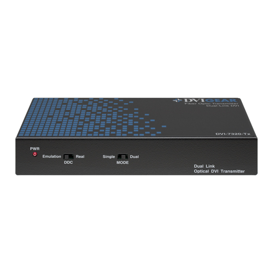
- Page 1 User Guide Dual-Link DVI Fiber Optic Extender DVI-7320...
-
Page 2: Table Of Contents
TABLE OF CONTENTS SECTION PAGE PRODUCT SAFETY ........1 PRODUCT LIABILITY . -
Page 3: Product Safety
Product Liability Every effort has been made to ensure that this product is free of defects. DVIGear cannot be held liable for the use of this product or for any direct or indirect consequential damages arising from its use. It is the responsibility of the users of this product to check that it is suitable for their requirements and that it is installed correctly. -
Page 4: Introduction
INTRODUCTION The DVI-7320 Dual-Link DVI Fiber Optic Extender enables the transmission of both single-link and dual-link DVI signals at distances up to 500 meters (100 meters with real DDC support) without any signal degradation. This makes it an ideal solution for applications where a dual-link DVI display must be extended from the signal source without introducing artifacts in the image. -
Page 5: Specifications
Operating: 32° to 122° F ( 0° to 50° C ); Storage: -4° to 158° F ( -20° to 70° C ) Humidity (storage/operating) 10 – 80% Power DVI-7320-Tx requires 300 ma of DC current from pin 14 of the DVI (source) connector. Optical Transmitter An optional external power adapter (DVI-7320-PS) may be used if needed. -
Page 6: Package Contents
CONNECTING THE HARDWARE This product consists of the DVI-7320-Tx Transmitter Unit and the DVI-7320-Rx Receiver Unit. The DVI-7320-Tx must be connected to the DVI output port of the signal source (such as a PC). The DVI-7320-Rx should be connected to the DVI input port of a digital display. - Page 7 Each unit has seven (7) Optical ports that are marked with the numbers T1, T2, T3, T4, T5, T6, and T7 on the DVI-7320-Tx unit, and R1, R2, R3, R4, R5, R6, and R7 on the DVI-7320-Rx unit. It is important to connect each LC fiber optic cable to the corresponding number on both the DVI-7320-Tx and DVI-7320-Rx units.
-
Page 8: Operating The Unit
DVI-7320-Tx unit. When the DVI source boots, up it reads the EDID information stored in the DVI-7320-Tx in the same way as if the display were connected directly to it. The DDC Emulation Mode eliminates the need for the copper DDC link;... -
Page 9: Troubleshooting
DVI-7320 extender pair. If there is still no image, then there is a compatibility issue between the source and the display that must be resolved. -
Page 10: Limited Warranty
In no event shall DVIGear be responsible or liable for any damage arising from the use of such defective products, including but not limited to loss of use, revenue or profit, whether such damages are direct, indirect, consequential or otherwise and whether such damages are incurred by the reseller, end-user, or any third-party. - Page 11 Your Digital Connectivity Experts Toll Free 888.463.9927 DVIGear, Inc. Phone 770.421.6699 1059 Triad Court, Suite 8 770.234.4207 Marietta, Georgia 30062-2258 www.dvigear.com DVI-7320-UG-04 / March.2018...
Need help?
Do you have a question about the DVI-7320 and is the answer not in the manual?
Questions and answers