
Related Manuals for Nordson EFD ValveMate 9000


Summary of Contents for Nordson EFD ValveMate 9000
- Page 1 ValveMate 9000 Controller Operating Manual ™ Electronic pdf files of Nordson EFD manuals are also available at www.nordsonefd.com...
- Page 2 Thank You! You have just purchased the world’s finest precision dispensing equipment. I want you to know that all of us at Nordson EFD value your business and will do everything in our power to make you a satisfied customer.
-
Page 3: Table Of Contents
Connect Driver Outputs ............................23 Connect Heater Outputs and Temperature Control Feedback ................24 Connect General Purpose Inputs / Outputs ......................25 Check the Component Installation ..........................26 Continued on next page www.nordsonefd.com info@nordsonefd.com 800-556-3484 Sales and service of Nordson EFD dispensing systems are available worldwide. - Page 4 General Purpose I/O and I/O Menus ........................75 Specific Alarms and Auto Increment ........................77 Miscellaneous ................................78 Appendix C, Driver Spike-and-Hold Technical Data .....................79 Appendix D, Settings Stored in Memory Cells ......................81 www.nordsonefd.com info@nordsonefd.com 800-556-3484 Sales and service of Nordson EFD dispensing systems are available worldwide.
-
Page 5: Introduction
ValveMate 9000 Controller Introduction The ValveMate 9000 dispensing valve controller includes a programmable dispensing time setting, digital time readout, keypad programming for easy user interface, and input / output (I/O) communication with host machine PLCs. Other features include: • Programmable fluid pressure and temperature settings •... -
Page 6: Nordson Efd Product Safety Statement
Hot surfaces! Avoid contact with the hot metal surfaces of heated components. If contact can not be avoided, wear heat-protective gloves and clothing when working around heated equipment. Failure to avoid contact with hot metal surfaces can result in personal injury. www.nordsonefd.com info@nordsonefd.com 800-556-3484 Sales and service of Nordson EFD dispensing systems are available worldwide. -
Page 7: Halogenated Hydrocarbon Solvent Hazards
Qualified personnel are those employees or contractors who are trained to safely perform their assigned tasks. They are familiar with all relevant safety rules and regulations and are physically capable of performing their assigned tasks. www.nordsonefd.com info@nordsonefd.com 800-556-3484 Sales and service of Nordson EFD dispensing systems are available worldwide. -
Page 8: Intended Use
Make sure all equipment is rated and approved for the environment in which it is used. Any approvals obtained for Nordson EFD equipment will be voided if instructions for installation, operation, and service are not followed. If the equipment is used in a manner not specified by Nordson EFD, the protection provided by the equipment may be impaired. -
Page 9: Fire Safety
• Test: Verify the operation of features and the performance of equipment using the appropriate sections of this manual. Return faulty or defective units to Nordson EFD for replacement. • Use only replacement parts that are designed for use with the original equipment. Contact your Nordson EFD representative for information and advice. -
Page 10: Important Disposable Component Safety Information
Disconnect and lock out system electrical power. If using hydraulic and pneumatic shutoff valves, close and relieve pressure. For Nordson EFD air-powered dispensers, remove the syringe barrel from the adapter assembly. For Nordson EFD electro-mechanical dispensers, slowly unscrew the barrel retainer and remove the barrel from the actuator. -
Page 11: Equipment-Specific Safety Information
Equipment-Specific Safety Information Safety Ground Connection Nordson EFD controllers are designed with a three-position IEC 60320-C14 receptacle that connects the ground line to the chassis ground. To minimize shock hazard, make sure your electrical power outlet and power cord have an appropriate earth safety ground that is connected whenever you power up the controller. -
Page 12: Specifications
Spike time: 20–250 ms , 5 ms resolution Setup method: (1) digital using the front panel keys or (2) remotely using a serial cable (RS-232C) Continued on next page www.nordsonefd.com info@nordsonefd.com 800-556-3484 Sales and service of Nordson EFD dispensing systems are available worldwide. - Page 13 WEEE Directive This equipment is regulated by the European Union under WEEE Directive (2012/19/EU). Refer to www.nordsonefd.com/WEEE for information about how to properly dispose of this equipment. www.nordsonefd.com info@nordsonefd.com 800-556-3484 Sales and service of Nordson EFD dispensing systems are available worldwide.
-
Page 14: Operating Features
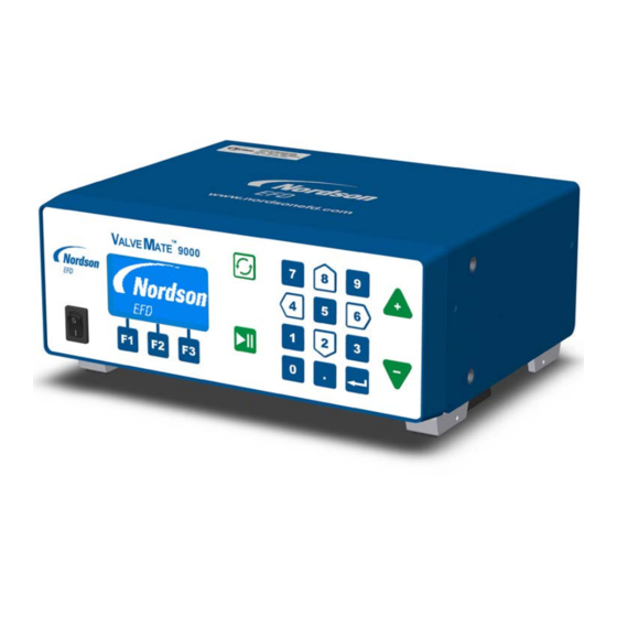
Use to adjust any numeric parameter keys Numeric keypad and LCD display DISPENSE key ARROW keys Power switch Function keys ENABLE/DISABLE ENTER key INCREASE (+)/ DECREASE (-) keys www.nordsonefd.com info@nordsonefd.com 800-556-3484 Sales and service of Nordson EFD dispensing systems are available worldwide. -
Page 15: Back Panel Components
Back Panel Components HEATER 1, HEATER 2, Foot pedal and DRV. OUT RS-232C connection connections connection I/O connection Ground AC power EXHAUST AIR IN terminal input port port www.nordsonefd.com info@nordsonefd.com 800-556-3484 Sales and service of Nordson EFD dispensing systems are available worldwide. -
Page 16: Back Panel Markings
This symbol identifies the chassis connection terminal. Use this terminal for grounding the chassis to shunt leakage current and / or enhance system ESD protection. Foot pedal Ground connection terminal www.nordsonefd.com info@nordsonefd.com 800-556-3484 Sales and service of Nordson EFD dispensing systems are available worldwide. -
Page 17: Installation
70 psi solenoid (4.8 bar) valve Fluid supply to dispensing valve AIR IN to EFD dispensing controller valve Fluid reservoir ValveMate 9000 Controller www.nordsonefd.com info@nordsonefd.com 800-556-3484 Sales and service of Nordson EFD dispensing systems are available worldwide. -
Page 18: Unpack The Controller Components
Hex wrench, hex key, 4 mm Connector, 4-position, P3.5 mm, female plug Connector, 16-position, P3.5 mm, female plug (Not Shown) Literature — Optimum Component Poster Complaints Card Quick-start guide www.nordsonefd.com info@nordsonefd.com 800-556-3484 Sales and service of Nordson EFD dispensing systems are available worldwide. -
Page 19: Install The Ancillary System Components
If you want to use the optional mounting bracket (PN 7013556), install it on the controller. A drill hole pattern is provided below. 3.81 MIN 2.50 96.8 MIN 63.5 15.2 10.13 MIN 257.2 MIN 11.66 4X R.19 MAX 296.3 4.8 MAX Mounting bracket drill pattern www.nordsonefd.com info@nordsonefd.com 800-556-3484 Sales and service of Nordson EFD dispensing systems are available worldwide. -
Page 20: Connect Power
The wire must have green insulation with a yellow stripe or must be noninsulated (bare). Attach the opposite end of the wire to a permanent earth ground using toothed washers or a toothed lug. www.nordsonefd.com info@nordsonefd.com 800-556-3484 Sales and service of Nordson EFD dispensing systems are available worldwide. -
Page 21: Connect Air
NOTE: Air output push-in fittings have an internal safety stop valve. Make sure the air line tubing is fully inserted into the fitting to allow proper air flow. www.nordsonefd.com info@nordsonefd.com 800-556-3484 Sales and service of Nordson EFD dispensing systems are available worldwide. -
Page 22: Air In Connection
Make sure the exhaust port is not restricted. If needed, connect air line tubing to the quick-connect fitting route the exhaust air to a remote location. EXHAUST connection (6 mm) www.nordsonefd.com info@nordsonefd.com 800-556-3484 Sales and service of Nordson EFD dispensing systems are available worldwide. -
Page 23: Connect Wiring
Use the supplied 4-position plug to connect each driver output signal to the solenoid valves for dispense valves 1 and 2. The controller provides two driver outputs. Each output is 24 W, 5–24 VDC. www.nordsonefd.com info@nordsonefd.com 800-556-3484 Sales and service of Nordson EFD dispensing systems are available worldwide. -
Page 24: Connect Heater Outputs And Temperature Control Feedback
• To prevent malfunction, ensure that the thermocouple is in close thermal contact with the heater. • Nordson EFD recommends using only heated valves that are compatible with this controller. www.nordsonefd.com info@nordsonefd.com 800-556-3484 Sales and service of Nordson EFD dispensing systems are available worldwide. -
Page 25: Connect General Purpose Inputs / Outputs
GPO 1–4+ General Purpose Outputs (GPOs)—these outputs turn on when triggered by the corresponding GPI. GOI 1–4- Isolated return path for the corresponding GPO+ pins I/O connection www.nordsonefd.com info@nordsonefd.com 800-556-3484 Sales and service of Nordson EFD dispensing systems are available worldwide. -
Page 26: Check The Component Installation
(0). On all EFD cartridge reservoirs, the unique threaded design provides fail-safe air pressure release during cap removal. www.nordsonefd.com info@nordsonefd.com 800-556-3484 Sales and service of Nordson EFD dispensing systems are available worldwide. -
Page 27: Setup
Accesses the GENERAL Resets CNT or PURPOSE IO screens clears latched Choices that can be selected by alarms pressing F1, F2, or F3 www.nordsonefd.com info@nordsonefd.com 800-556-3484 Sales and service of Nordson EFD dispensing systems are available worldwide. -
Page 28: Navigating Through The Controller Screens
The VM9000 Controller Key Legend shows the terms used in this manual for each key. VM9000 Controller Key Legend INCREASE (+) key DECREASE (-) key ENTER key DISPENSE key ARROW keys ENABLE/DISABLE key www.nordsonefd.com info@nordsonefd.com 800-556-3484 Sales and service of Nordson EFD dispensing systems are available worldwide. - Page 29 ValveMate 9000 Controller Setup (continued) Flowchart of Controller Screens www.nordsonefd.com info@nordsonefd.com 800-556-3484 Sales and service of Nordson EFD dispensing systems are available worldwide.
-
Page 30: Connecting The Controller To A Computer
If desired, use the supplied RS-232C cable to connect the controller to a laptop, PC, or PLC. Refer to “Setting the RS-232C Baud Rate” to change the baud rate. Appendix B, “RS-232C Connection Protocol,” is provided for your reference as needed. www.nordsonefd.com info@nordsonefd.com 800-556-3484 Sales and service of Nordson EFD dispensing systems are available worldwide. -
Page 31: Enabling / Disabling The Controller
NOTE: Although the controller can be programmed in both the enabled and disabled modes, Nordson EFD strongly recommends programming the controller in the disabled mode to prevent erratic operation. Once all changes have been made, the controller can be enabled. -
Page 32: Setting Units Of Pressure
MAIN MENU, press F3. VM9000 Controller Key Legend INCREASE (+) key DECREASE (-) key ENTER key DISPENSE key ARROW keys ENABLE/DISABLE key www.nordsonefd.com info@nordsonefd.com 800-556-3484 Sales and service of Nordson EFD dispensing systems are available worldwide. -
Page 33: Entering Driver Spike-And-Hold Settings
Press F2 two more times to return to the MAIN screen. CAUTION Risk of solenoid valve damage. If you are using dispense valve 745NC with a 24 W solenoid, Nordson EFD strongly recommends using the spike-and-hold functionality and not exceeding a DRV SPIKE TIME of 30 ms and a DRV HOLD VOLTS of 5 V. -
Page 34: Setting Up The Driver Outputs
DRIVERS screen, page 2 VM9000 Controller Key Legend INCREASE (+) key DECREASE (-) key ENTER key DISPENSE key ARROW keys ENABLE/DISABLE key www.nordsonefd.com info@nordsonefd.com 800-556-3484 Sales and service of Nordson EFD dispensing systems are available worldwide. - Page 35 The SHOT CNT parameter increases by one for every cycle the driver is on, not every initiate. Press ENTER to reset SHOT CNT to 00000000. www.nordsonefd.com info@nordsonefd.com 800-556-3484 Sales and service of Nordson EFD dispensing systems are available worldwide.
-
Page 36: Setting Up Pressure Control
Shows the actual pressure of the pressure channel. ALARM — Refer to “Clearing Alarms.” VM9000 Controller Key Legend INCREASE (+) key DECREASE (-) key ENTER key DISPENSE key ARROW keys ENABLE/DISABLE key www.nordsonefd.com info@nordsonefd.com 800-556-3484 Sales and service of Nordson EFD dispensing systems are available worldwide. -
Page 37: Setting Up Heater Control
Shows the actual temperature of the heater channel. ALARM — Refer to “Clearing Alarms.” VM9000 Controller Key Legend INCREASE (+) key DECREASE (-) key ENTER key DISPENSE key ARROW keys ENABLE/DISABLE key www.nordsonefd.com info@nordsonefd.com 800-556-3484 Sales and service of Nordson EFD dispensing systems are available worldwide. -
Page 38: Setting Up The General Purpose I/Os
GENERAL PURPOSE IO screen, page 2 VM9000 Controller Key Legend INCREASE (+) key DECREASE (-) key ENTER key DISPENSE key ARROW keys ENABLE/DISABLE key www.nordsonefd.com info@nordsonefd.com 800-556-3484 Sales and service of Nordson EFD dispensing systems are available worldwide. - Page 39 The number of seconds the channel turns on. (CYCL mode) 1 ms increments) 0.001 to 99.999 (sec, in The number of seconds the channel turns off. (CYCL mode) 1 ms increments) www.nordsonefd.com info@nordsonefd.com 800-556-3484 Sales and service of Nordson EFD dispensing systems are available worldwide.
-
Page 40: Entering Memory Cell Settings
VM9000 Controller Key Legend INCREASE (+) key DECREASE (-) key ENTER key DISPENSE key ARROW keys ENABLE/DISABLE key www.nordsonefd.com info@nordsonefd.com 800-556-3484 Sales and service of Nordson EFD dispensing systems are available worldwide. -
Page 41: Setting Up The Auto Increment Mode
MAIN MENU, press F3. VM9000 Controller Key Legend INCREASE (+) key DECREASE (-) key ENTER key DISPENSE key ARROW keys ENABLE/DISABLE key www.nordsonefd.com info@nordsonefd.com 800-556-3484 Sales and service of Nordson EFD dispensing systems are available worldwide. - Page 42 RESET on the MAIN screen and presses the ENTER key twice. After a reset, the controller returns to the STRT memory cell and CNT resets to 0000. www.nordsonefd.com info@nordsonefd.com 800-556-3484 Sales and service of Nordson EFD dispensing systems are available worldwide.
- Page 43 Example: Set AI SYNC to CH2 if you want to tie the Auto Increment Mode to the number of shots dispensed from Driver 2 instead of Driver 1. Auto Increment Mode functions Use to reset CNT or clear an AI alarm www.nordsonefd.com info@nordsonefd.com 800-556-3484 Sales and service of Nordson EFD dispensing systems are available worldwide.
-
Page 44: Entering The Auto Increment Mode Alarm Setting
Press F2 again to return to the MAIN screen. Auto Increment Mode System Alarm screen VM9000 Controller Key Legend INCREASE (+) key DECREASE (-) key ENTER key DISPENSE key ARROW keys ENABLE/DISABLE key www.nordsonefd.com info@nordsonefd.com 800-556-3484 Sales and service of Nordson EFD dispensing systems are available worldwide. -
Page 45: Entering Pressure Alarm Settings
Pressure System Alarm screen VM9000 Controller Key Legend INCREASE (+) key DECREASE (-) key ENTER key DISPENSE key ARROW keys ENABLE/DISABLE key www.nordsonefd.com info@nordsonefd.com 800-556-3484 Sales and service of Nordson EFD dispensing systems are available worldwide. -
Page 46: Entering Heater Alarm Settings
Heat system Alarm screen VM9000 Controller Key Legend INCREASE (+) key DECREASE (-) key ENTER key DISPENSE key ARROW keys ENABLE/DISABLE key www.nordsonefd.com info@nordsonefd.com 800-556-3484 Sales and service of Nordson EFD dispensing systems are available worldwide. -
Page 47: Setting Alarm Options
Press F2 again to return to the MAIN screen. Input Alarm System Alarm screen VM9000 Controller Key Legend INCREASE (+) key DECREASE (-) key ENTER key DISPENSE key ARROW keys ENABLE/DISABLE key www.nordsonefd.com info@nordsonefd.com 800-556-3484 Sales and service of Nordson EFD dispensing systems are available worldwide. - Page 48 ALARM on the HEATERS screen and pressing ENTER, or (2) by selecting RESET on the MAIN screen and pressing ENTER two times, after the cause of the alarm has been removed. Refer to “Clearing Alarms.” www.nordsonefd.com info@nordsonefd.com 800-556-3484 Sales and service of Nordson EFD dispensing systems are available worldwide.
-
Page 49: Setting The Rs-232C Baud Rate
Press F2 again to return to the MAIN screen. VM9000 Controller Key Legend INCREASE (+) key DECREASE (-) key ENTER key DISPENSE key ARROW keys ENABLE/DISABLE key www.nordsonefd.com info@nordsonefd.com 800-556-3484 Sales and service of Nordson EFD dispensing systems are available worldwide. -
Page 50: Adjusting The Lcd Contrast
Press F2 to return to the MAIN screen. VM9000 Controller Key Legend INCREASE (+) key DECREASE (-) key ENTER key DISPENSE key ARROW keys ENABLE/DISABLE key www.nordsonefd.com info@nordsonefd.com 800-556-3484 Sales and service of Nordson EFD dispensing systems are available worldwide. -
Page 51: System Startup And Operation
CAUTION Risk of solenoid valve damage. If you are using dispense valve 745NC with a 24 W solenoid, Nordson EFD strongly recommends using the spike-and-hold functionality and not exceeding a DRV SPIKE TIME of 30 ms and a DRV HOLD VOLTS of 5 V. -
Page 52: Clearing Alarms
NOTE: Refer to “Entering Pressure Alarm Settings” and “Entering Heater Alarm Settings” to enable alarms. Refer to “Setting Alarm Options” to latch or unlatch alarms. Flashing Pressure System Alarm screen Flashing Heater System Alarm screen www.nordsonefd.com info@nordsonefd.com 800-556-3484 Sales and service of Nordson EFD dispensing systems are available worldwide. -
Page 53: Clearing An Alarm Input Or Auto Increment Mode Alarm
“Setting Alarm Options” to latch or unlatch an Alarm Input alarm. Refer to “Entering the Auto Increment Mode Alarm Setting” to enable the Auto Increment Mode alarm. Flashing Input Alarm System Alarm screen Flashing Auto Increment Mode System Alarm screen www.nordsonefd.com info@nordsonefd.com 800-556-3484 Sales and service of Nordson EFD dispensing systems are available worldwide. -
Page 54: Clearing A Heater Fault Alarm
SET temperature to allow the controller enough time to reach the desired temperature setting. In a normal, room-temperature. In a normal, room-temperature environment, Nordson EFD valves rarely require more than 1 minute to be within 10º C of SET temperature. -
Page 55: Clearing A Thermocouple (Tc) Fault Alarm
On the HEATERS screen, select either ALARM and press ENTER to clear the alarm. NOTE: You can also clear a TC Fault alarm by pressing the ENABLE/DISABLE key to disable the controller. www.nordsonefd.com info@nordsonefd.com 800-556-3484 Sales and service of Nordson EFD dispensing systems are available worldwide. -
Page 56: Troubleshooting
Remove or disable the system alarm. The unit will not initiate if there Alarm IN is an input alarm present. Refer to “Clearing an Alarm Input or Auto Increment Mode Alarm.” Continued on next page www.nordsonefd.com info@nordsonefd.com 800-556-3484 Sales and service of Nordson EFD dispensing systems are available worldwide. - Page 57 Problem with wiring Ensure that the wiring is correctly stripped and that the conductors are integrity making contact with the screw terminal connector. Continued on next page www.nordsonefd.com info@nordsonefd.com 800-556-3484 Sales and service of Nordson EFD dispensing systems are available worldwide.
- Page 58 Ensure that the initiate signal is applied to the same GPI channel as it is wrong pins for the desired GPO channel. Continued on next page www.nordsonefd.com info@nordsonefd.com 800-556-3484 Sales and service of Nordson EFD dispensing systems are available worldwide.
- Page 59 Verify that the ON time settings are within the working range of the valve. not actuating Unable to Heater control loop Contact Nordson EFD. regulate Valve parameters not temperature adjusted for a non- Nordson EFD valve www.nordsonefd.com info@nordsonefd.com 800-556-3484 Sales and service of Nordson EFD dispensing systems are available worldwide.
-
Page 60: Part Number
KIT, REPLACEMENT FUSES, VM9000 (2) (for the AC power cord plug) 7029778 KIT, BEZEL AND OVERLAY, VM9000 7014547 KIT, POWER SWITCH, ULTIMUS V (Not 7013556 KIT, PANEL MOUNT (mounting bracket for the controller) Shown) www.nordsonefd.com info@nordsonefd.com 800-556-3484 Sales and service of Nordson EFD dispensing systems are available worldwide. -
Page 61: Appendix A, Connector Pin Technical Data
J-type thermocouple connection The wire color is red. Constantan (Cu-Ni) HT2+ Same as HT1+ HT2- Return path for HT2+ output TC2+ Same as TC1+ TC2- Same as TC1- www.nordsonefd.com info@nordsonefd.com 800-556-3484 Sales and service of Nordson EFD dispensing systems are available worldwide. -
Page 62: Driver Outputs
20–250 ms (adjustable) • Hold voltage of 5–24 V (adjustable) DRV.OUT 1- Return path for DRV1+ output DRV.OUT 2+ Same as DRV1+ DRV.OUT 2- Same as DRV1- www.nordsonefd.com info@nordsonefd.com 800-556-3484 Sales and service of Nordson EFD dispensing systems are available worldwide. -
Page 63: Foot Pedal Connector
VDC, 20 mA maximum, reverse polarity protected, 10 ms minimum pulse and not isolated. Foot Pedal Connector Schematic I/O Pin Name AI+ : AI- CC+ : CC- www.nordsonefd.com info@nordsonefd.com 800-556-3484 Sales and service of Nordson EFD dispensing systems are available worldwide. -
Page 64: I/O Connector
“Setting Alarm Options.” • AI closure sense input • 5–24 VDC • 20 mA maximum • reverse-polarity protected • 10 ms minimum pulse, not isolated Continued on next page www.nordsonefd.com info@nordsonefd.com 800-556-3484 Sales and service of Nordson EFD dispensing systems are available worldwide. - Page 65 • Same as GPI1- above GPI4+ • Same as GPI1+ above Refer to the General Purpose Input 1 signal description. GPI4- • Same as GPI1- above Continued on next page www.nordsonefd.com info@nordsonefd.com 800-556-3484 Sales and service of Nordson EFD dispensing systems are available worldwide.
-
Page 66: I/O Connector Schematics
• Ground return and reference for the 24 VDC output I/O Connector Schematics I/O Pin Name GPO1+ : GPO1- GPO2+ : GPO2- GPO3+ : GPO3- GPO4+ : GPO4- www.nordsonefd.com info@nordsonefd.com 800-556-3484 Sales and service of Nordson EFD dispensing systems are available worldwide. - Page 67 GPI2+ : GPI2- GPI3+ : GPI3- GPI4+ : GPI4- I/O Pin Name PS1+ : G1- PS2+ : G2- I/O Pin Name AI+ : AI- CC+ : CC- www.nordsonefd.com info@nordsonefd.com 800-556-3484 Sales and service of Nordson EFD dispensing systems are available worldwide.
-
Page 68: Appendix B, Rs-232C Connection Technical Information
RS-232C Protocol Communication Specifications The RS-232C protocol for the ValveMate 9000 controller uses the RS-232C standard. The controller acts as a terminal to the remote host PC or PLC. The controller communicates using the following settings: • Synchronous mode: half duplex •... -
Page 69: Rs-232C Commands
In this example, the controller did not recognize the command “0DISK” because all commands are case-sensitive. RS-232C Commands The following tables provide the RS-232C commands for the ValveMate 9000 controller. Each entry includes a brief description of the command, shows the command format, and provides a description of the data that is attached and retrieved by the command. -
Page 70: Main Menu And Main Screen
Returns the current main screen settings Host Format: rman rman [Enter] Feedback of the controller STRT = 05 END = 20 MEM = 05 TRIG = 3030 CNT = 0000 www.nordsonefd.com info@nordsonefd.com 800-556-3484 Sales and service of Nordson EFD dispensing systems are available worldwide. -
Page 71: Temperature Menu
Returns the current settings for Host Format: rht2 rht2 [Enter] Channel 2 heater 2 MEM = 00 Feedback MODE = ON SET = 27F ACT = ---F www.nordsonefd.com info@nordsonefd.com 800-556-3484 Sales and service of Nordson EFD dispensing systems are available worldwide. -
Page 72: Pressure Menu
Returns the current settings for Host Format: tpr2 tpr2 [Enter] Channel 2 pressure channel 2 MEM = 00 Feedback MODE = OFF SET = 060.8p ACT = 000.0p www.nordsonefd.com info@nordsonefd.com 800-556-3484 Sales and service of Nordson EFD dispensing systems are available worldwide. -
Page 73: Driver Menu
Driver 2 Spike and Hold Hold Mode is OFF 1hld2 Sets spike and hold mode to ON 1hld2 [Enter] Driver 2 Spike and Hold is ON Continued on next page www.nordsonefd.com info@nordsonefd.com 800-556-3484 Sales and service of Nordson EFD dispensing systems are available worldwide. - Page 74 MEM = 00 MODE = OFF ON TIME = 0.1584 OFF TIME = 9.4513 DCNT = 7890 Spike and Hold = ON Volts = 15 Count = 00450498 www.nordsonefd.com info@nordsonefd.com 800-556-3484 Sales and service of Nordson EFD dispensing systems are available worldwide.
-
Page 75: General Purpose I/O And I/O Menus
4gpi4 Reads back the status of GPIO 4 GPIO 4: STDY (OFF/ON/STDY/CYCL) 3gpi4 [Enter] GPIO 4: CYCL 4gpi4 [Enter] GPIO 4: CYCL Continued on next page www.nordsonefd.com info@nordsonefd.com 800-556-3484 Sales and service of Nordson EFD dispensing systems are available worldwide. - Page 76 DELAY: 66.679 GPIO 4 Retrieves the current setup Host Format: rgp4 rgp4 [Enter] Feedback parameters for GPIO 4 GPIO 4 Mode: STDY TIME: 00.050 DELAY: 33.984 www.nordsonefd.com info@nordsonefd.com 800-556-3484 Sales and service of Nordson EFD dispensing systems are available worldwide.
-
Page 77: Specific Alarms And Auto Increment
Auto Increment Alarm Disabled Auto Increment ALARM OFF Alarm 1aial Auto Increment Alarm Enabled 1aial [Enter] 2aial Auto Increment Alarm Auto Increment ALARM ON Feedback Continued on next page www.nordsonefd.com info@nordsonefd.com 800-556-3484 Sales and service of Nordson EFD dispensing systems are available worldwide. -
Page 78: Miscellaneous
Host Format: info info [Enter] Information of the ValveMate 9000 7028693-VM 9000 controller V:001.001 1/1/14 System Performs a soft reboot Host Format: boot boot [Enter] Reboot www.nordsonefd.com info@nordsonefd.com 800-556-3484 Sales and service of Nordson EFD dispensing systems are available worldwide. -
Page 79: Appendix C, Driver Spike-And-Hold Technical Data
30 ms. To prevent damage to the actuation solenoid, the ValveMate 9000 controller provides a spike-and-hold functionality. When properly set, the spike-and-hold functionality allows the controller to spike the voltage for a user-specified spike time (DRV SPIKE TIME) and then throttle the voltage down to a user-specified hold voltage (DRV HOLD VOLTS) after the spike time expires. - Page 80 ValveMate 9000 Controller Appendix C, Driver Spike-and-Hold Technical Data (continued) Scope Plot of the Spike-and-Hold Functionality 20 ms 24 V 100 ms www.nordsonefd.com info@nordsonefd.com 800-556-3484 Sales and service of Nordson EFD dispensing systems are available worldwide.
-
Page 81: Appendix D, Settings Stored In Memory Cells
• Mode 2 • Temperature Setting 1 • Temperature Setting 2 Pressure • Mode 1 • Mode 2 • Set Pressure 1 • Set Pressure 2 www.nordsonefd.com info@nordsonefd.com 800-556-3484 Sales and service of Nordson EFD dispensing systems are available worldwide. - Page 82 NORDSON EFD ONE YEAR LIMITED WARRANTY All components of the Nordson EFD ValveMate 9000 are warranted for one year from date of purchase to be free from defects in material and workmanship (but not against damage caused by misuse, abrasion, corrosion, negligence, accident, faulty installation or by dispensing material incompatible with equipment) when the equipment is installed and operated in accordance with factory recommendations and instructions.
Need help?
Do you have a question about the ValveMate 9000 and is the answer not in the manual?
Questions and answers