
Related Manuals for Omron CR_UDG4_NR


Summary of Contents for Omron CR_UDG4_NR
- Page 1 Cat. No. I192E-EN-01 Delta Robot ZX-T Series CR_UGD4 Series Delta Robot USER´S MANUAL...
-
Page 3: Table Of Contents
CONTENTS CR_UGD4 User's Manual Safety Instructions 1. Attention 2. Explanation of warnings and notes 3. Safety information 3.1 General 3.2 Qualified personnel 3.3 Liability 3.4 Installation and operating conditions 3.5 Residual risks 3.5.1 Release device 3.5.2 Transport 3.5.3 Assembly and start-up 3.5.4 Maintenance and repair 3.5.5... - Page 4 CONTENTS CR_UGD4 User's Manual 3.3 Mounting the motor covers 3.4 Mounting the rotation motor or gearbox with his adaptor ring 4. Assembling the secondary arms 4.1 Make an assembly 4.2 Mount the arm assembly on the robot 5. Mounting the rotational axis on the motor/gearbox shaft 6.
-
Page 5: Safety Instructions
Safety Instructions Contents Attention Explanation of warnings and notes Safety information General Qualified personnel Liability Installation and operating conditions Residual risks 3.5.1 Release device 3.5.2 Transport 3.5.3 Assembly and start-up 3.5.4 Maintenance and repair 3.5.5 System integrator... -
Page 7: Attention
Information in this document can change without prior notice. OMRON EUROPE B.V. cannot be hold responsible for any damage to the environment, to the machine or to the functioning of the machine occurred by errors or missing data in the illustrations, drawing or specifications. -
Page 8: Safety Information
Safety information General This ´3. Safety information´ subchapter contains information regarding working with the CR_UGD4 robot. Qualified personnel working with the CR_UGD4 robot must have read and understood the CR_UGD4 robot documentation, including the safety information chapter. Qualified personnel These are people who, due there specialist training, knowledge and experience, and their familiarization with the relevant standards, are able to assess the work to be carried out and detect any potential hazards. -
Page 9: Release Device
3.5.1 Release device The robot mechanics are not supplied with an release switch to control the brakes of the motors. WARNING • MOuNt a RElEaSE SwItch ON thE MachINE SO thE aRMS (MOtOR) Of thE ROBOt cOulD BE MaNually MOVED. • MOvINg aN axIS wIth aN IMPROPERly wORkINg RElEaSE SwItch caN DaMagE thE MOtOR BRakE. thIS CAN RESULT IN PERSONAL INjURy AND MATERIAL DAMAGE. • BEfORE RElEaSINg thE BRakE, yOu havE tO BE SuRE that NO ONE IS IN thE hazaRD aREa Of thE ROBOt. 3.5.2 Transport The prescribed transport position of the robot must be observed. Transportation must be carried out in accordance with the transportation instructions or assembly instructions of the robot. -
Page 10: System Integrator
3.5.5 System integrator The robot is safely integrated into a complete system by the system integrator. The system integrator is responsible for the following tasks: • Installing the robot • Performing risk assessment • Implementing the required safety functions and safequards • Issuing the declaration of conformity • attaching the cE mark • creating the operating instructions for the complete system... -
Page 11: Introduction
Chapter 1 Introduction Contents Introduction Description of the robot Type code explanation Identification Part names... -
Page 13: Description Of The Robot
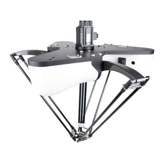
Introduction Congratulations with the purchase of your high speed Delta robot. This is a high speed pick and place robot which uses state-of-the-art carbon composite materials and the latest servo drive technology to be put in use in the most demanding pick and place applications. -
Page 14: Part Names
Part names CR_UGD4 Primary arm Rotary servo motor Motor connector Encoder connector Rotational axis Motor cover Secondary arm TCP (Tool Center Point) the cR_ugD4 robot consists of three radially placed axis which give the tcP freedom to move in three directions, x, y and z. An optional fourth axis can take care of the rotation, Rz, of the TCP. Optionally the robot is equipped with an extra servo motor for the rotational axis. -
Page 15: Chapter 2 Model Overview
Chapter 2 Model overview Contents Overview... -
Page 17: Overview
Overview The CR_UGD4 has a working range of 1100 mm. The specifications are given in the below figure, if specifications differ for models, for instance with- or without rotation axis, it is indicated in the specification list. The Delta robot is delivered standard with sanitary secondary arms, this means they are fully closed to prevent any contamination on the inside of the secondary arms. -
Page 19: Chapter 3 Installation
Chapter 3 Installation Contents Unpacking Unpacking the shipping box Check the damage Lifting and transportation Mounting the robot Mounting the motors and cabling Mounting the motors Connecting the cables Mounting the motor covers Mounting the rotation motor or gearbox with his adaptor ring Assembling the secondary arms Make an assembly Mount the arm assembly on the robot... -
Page 21: Unpacking
Unpacking Unpacking the shipping box The robot comes in a special shipping box. The following step must be carried out to remove the cover from the box: • unscrew the screws from the cover of the wooden box • Now remove the cover Check the damage first take out the individual components from the package and check that everything is complete according to the following list: • 1 x rotational axis (in case of cR_ugD4_R model) • 1 x adaptor ring for the rotational axis gear or motor (in case of cR_ugD4_R model) - Page 22 WARNING • thE ROBOt May tIlt DuRINg tRaNSPORtatION. • aDDItIONal SafEguaRDINg MEaSuRE MuSt BE takEN. • wEaR SuItaBlE PROtEctIvE clOthINg If NEcESSaRy. • whEN uSINg a fORklIft tRuck, DRIvE ExtREMEly SlOwly aND caREfully. Description Lifting tackle 2 x lifting straps 2 x eyebolts...
-
Page 23: Mounting The Robot
Mounting the robot The mounting surface for the robot must be machined and of an appropriate quality. It’s also possible to use a levelling element to align the robot. Three M16 bolts are needed to mounting the robot to the frame, exact bolt length depends on frame layout. The tightening torque of a M16 6.8 bolt is 140Nm. -
Page 24: Mounting The Motors And Cabling
Mounting the motors and cabling Mounting the motors When your robot is delivered without motors, you have to mount them by yourself. first of all you have to remove the three motor covers from the robot. The following steps must be carried out to remove the motor covers from the robot. Please see also the following picture: • Remove the M6 allen bolt Description... -
Page 25: Mounting The Motor Covers
Description 4 x M5 Allen bolt Cable entry glands Blind thule • Insert the cables into the opening of the robot baseplate • connect the cables • clamp the cable entry glands around the cable and slide it back into the cable entry plate. afterwards also slide the blind thule back into the cable entry plate • Mount the cable entry plate on the baseplate, using the 4 M5 allen bolts Mounting the motor covers • Mount the cover in the machined groove • Install the allen M6 bolt in the cover bracket and tighten • Repeat the process for the other two motor covers • the motor covers are now mounted Description Cover bracket Machined groove... -
Page 26: Mounting The Rotation Motor Or Gearbox With His Adaptor Ring
Mounting the rotation motor or gearbox with his adaptor ring this section is applicable only to the cR_ugD4_R model (with rotational axis). Dependent on the type of rotation motor or gearbox with rotation motor, a special adaptor ring for mounting is included. Description Gearbox or motor Adaptor ring Now mount the adaptor ring (with the motor or gearbox) on the top of the baseplate from the robot with the included bolts and rings. Description Top of the baseplate Rotation adaptor ring with motor or gearbox... -
Page 27: Assembling The Secondary Arms
Assembling the secondary arms Make an assembly Before mounting the secondary arms on the robot, we have to pre-assemble them as shown on the below figure, so that we get an arm assembly. Description Sanitary cup holder incl. ball bearing cup Spring package Secondary arm Repeat this action for the other 2 arm sets. -
Page 28: Mount The Arm Assembly On The Robot
Mount the arm assembly on the robot for mounting, pull a secondary arm with his cup holder over the ball joint of the primary arm. Now pull the arms apart against the force of the spring in order to pull the second arm over the second ball joint of the primary arm. then repeat this action for the tcP (see below picture). -
Page 29: Mounting The Rotational Axis On The Motor/Gearbox Shaft
Please perform the following steps first. • Extend the rotational axis to its entire length, then retract the same and check whether it is easy to operate or whether some resistance occurs NOTE a light irregular resistance is normal and caused by the manufacturing tolerances of the tubes. the axis is run in during the first 150 hours of operation. In case of problems, please check the axis for damage or contact your OMRON representative. Description Clamping bush with bolts Rotational axis Release the two M5 allen bolts which are mounted into the clamping bush (see above picture). In delivery condition, an extra fill bush is located in the clamping bush. -
Page 30: Calibration
Description Motor or gear shaft Top connector rotational axis Now push the top connector into the shaft until the top connector comes into its stop position on the shaft. Tighten the two M5 Allen bolts with 7 Nm. The rotational axis is now mounted. Calibration No every robot that is delivered is calibrated. - Page 31 • Now tighten the star nut until the tool is fixed • Release the motor brake from the selected motor and push the upper arm with his ball joint against the calibration tool as shown above • Now fix the motor brake from the selected motor • Repeat the calibration steps for the other two primary arms • Remove the tool WARNING • calIBRatINg thE ROBOt MuSt BE caRRIED Out By QualIfIED PROgRaMMINg PERSONNEl ONly, aS thIS REQuIRES aN ExcEllENt lEvEl Of kNOwlEDgE Of thE cONtROl SyStEM. • whEN caRRyINg Out thE hOMINg yOuRSElf, thIS MuSt BE caRRIED Out Exactly IN thE way aND thE ORDER ThAT ThEy ARE DESCRIBED. • Now all the primary arms are in zero position from the kinematic model • Now put the encoder values from the servo motors in 0° • check that the angle indicated for the three motors is 0° (±0.1°) • your robot is now calibrated 3-11...
-
Page 33: Chapter 4 Maintenance
Chapter 4 Maintenance Contents Periodic maintenance Springs Ball bearing cups Rotational axis Cleaning the robot Spare parts... -
Page 35: Periodic Maintenance
SAfEGUARDS ARE DEACTIVATED DURING MAINTENANCE OR REPAIR WORK, ThEy MUST BE REACTIVATED IMMEDIATELy AfTER ThE WORK IS COMPLETED. Springs how to maintain the springs: • the springs has to be replaced every 3800 working hours or once a year • when the robot is fall apart, check the springs on damages • Only use springs delivered by OMRON, otherwise the guarantee will expire • Replace springs after overstretching • for spare parts, see Section 3 Spare parts in this chapter WARNING • INcORREct MOuNtED SPRINgS caN juMP away. • wEaR SuItaBlE PROtEctIvE clOthINg aND SafEty glaSSES. -
Page 36: Ball Bearing Cups
Ball bearing cups The ball bearing cups has the same lifetime as the springs. We recommend to exchange these at the same time as the springs. how to maintain the ball bearing cups: • the ball bearing cups has to be replaced every 3800 working hours or once a year • when the ball bearing cups make squeaking noises, take of the secondary arm assembly’s and clean the cups with pressed air • Do not lubricate the ball bearing cups! for instructions to replace the ball bearing cups, see below picture: Description M5 bolt... - Page 37 Description M5 bolt with washer Slider clamp bottom Plain bearing • unscrew the two M5 bolts with washer and take of the slider clamp bottom • Now exchange the old bearing with a new one • Put back the slider clamp bottom and the two M5 bolts with washer • Repeat this for the other side of the axis Description 2 x M5 bolt with washer Slider clamp top 1 x M5 bolt with washer Top connector • unscrew the three M5 bolts with washer from the top connector and the slider clamp top • Remove the top connector from the tubes • Remove the slider clamp top with the plain bearings • Now exchange the old plain bearings with the new ones • Put back the slider clamp top and the M5 bolt with washer...
-
Page 38: Cleaning The Robot
Do not use a high pressure water cleaner, or any other high pressure cleaning device. Spare parts Description OMRON Part No. Ball bearing cups CR_ART.1002 Secondary round arm assembly CR_ART.1006-1 Calibration tool CR_ART.1007... -
Page 39: Chapter 5 Robot Settings
Chapter 5 Robot settings Contents Kinematics Workspace Software limits... -
Page 41: Kinematics
Kinematics The kinematics parameters for the CR_UGD4 robot are shown below. Set these parameters corresponding to the controller settings. WARNING If ThE KINEMATICS PARAMETERS ARE NOT SET PROPERLy, ThIS MAy CAUSE ThE ROBOT TO MALfUNCTION. SO, BE SURE TO SET ThESE PARAMETERS CORRECTLy. Kinematics parameters (mm) 200 mm Distance (radius) from the center of the fixed frame to the motor of the axis... -
Page 42: Workspace
Workspace The workspace parameters for the CR_UGD4 robot are shown below. Set these parameters corresponding to the controller settings. WARNING If ThE WORKSPACE PARAMETERS ARE NOT SET PROPERLy, ThIS MAy CAUSE ThE ROBOT TO MALfUNCTION. SO, BE SURE TO SET ThESE PARAMETERS CORRECTLy. Workspace parameters -616 mm Distance from the Z-axis origin position Rcy:... -
Page 43: Software Limits
Software limits The software limits for the CR_UGD4 robot are shown below. WARNING α- β- γ- If ThE axIS SOft lIMIt IS SEt INcORREctly, thE aRM May cOllIDE wIth thE ROBOt BaSE OR BaSE PREPARED By ThE USER, CAUSING BREAKAGE. SO, BE SURE TO SET ThE SOfT LIMITS CORRECTLy. Minus direction soft limit [-47°] Plus direction soft limit [99°]... -
Page 45: Chapter 6 Specifications
Chapter 6 Specifications Contents Basic specifications Cycle time External view and dimensions Design specifications Occupation area of robot Gripper interface Software design 3.3.1 Dimensions and limits... -
Page 47: Basic Specifications
Basic specifications Robot model CR_UDG4_R CR_UDG4_NR x, y axis Stroke 1100mm Ø z axis Stroke 250mm (max. Ø1100mm)/400mm (center Ø580mm) Working volume ±180° (default setting, it can be θ axis Rotation range changed) Arm 1, 2, 3 1000W Servo motor Rotational axis 4 1000W x, y, z axis ±0.3mm Repeatability θ axis ±0.4° Maximum through-put 150 CPM Maximum payload θ axis tolerable moment of inertia... -
Page 48: External View And Dimensions
External view and dimensions... -
Page 49: Design Specifications
Design specifications Occupation area of robot If the robot is integrated into the machine it must be considered what the reach is of all robot parts to prevent collision with other parts in the machine. When the TCP moves to its outer positions, the primary and secondary arms can rise above the baseplate, take care that no mechanical obstructions are in the areas indicated in the below figure. -
Page 50: Software Design
The design of the gripper that is mounted under the robot have great influence on the performance of the robot. Both the weight of the gripper and the distance of the center of gravity of the gripper to the TCP base point have negative influence on the final performance of the robot. -
Page 51: Dimensions And Limits
3.3.1 Dimensions and limits Description Value Negative software limit -47º Positive software limit 99º tb-z (top baseplate to zero position) 90 mm z-tw (zero position to top work area) 660 mm Neg.° Top mounting bracket Tb-z Primary arm 0° Z-tw Pos.° Top work area... - Page 53 Revision history a manual revision code appears as a suffix to the catalog number on the front cover manual. Cat. No. I192E-EN-01 Revision code The following table outlines the changes made to the manual during each revision. Revision code Date Description june 2015 Original production...
- Page 54 Authorized Distributor: Cat. No. I192E-EN-01 Note: Specifications subject to change without notice. Printed in Europe...
Need help?
Do you have a question about the CR_UDG4_NR and is the answer not in the manual?
Questions and answers