Table of Contents
Advertisement
Quick Links
Advertisement
Table of Contents

Related Manuals for Sonel TDR-420


Summary of Contents for Sonel TDR-420
- Page 3 USER MANUAL TDR CABLE FAULT LOCATOR TDR-420 SONEL S.A. Wokulskiego 11 58-100 Świdnica Version 1.00 06.04.2018...
- Page 4 TDR-420 is a modern, high-quality measuring device, easy and safe to use. Please acquaint yourself with this manual in order to avoid measuring errors and prevent possible problems in operation of the meter. TDR-420 – USER MANUAL...
-
Page 5: Table Of Contents
11 Dismantling and Disposal ................ 21 12 Typical images of damaged cables ............22 13 Typical values of VoP and impedance Z..........23 14 Technical data ................... 25 15 Accessories ....................26 16 Manufacturer ..................... 26 17 Laboratory services .................. 27 TDR-420 – USER MANUAL... -
Page 6: Introduction
The shortest measuring range is 7 meters and a dead zone of 0.6 m. TDR-420 displays the signals from the tested cable as a "trace" i.e. a waveform similar to an os- cilloscope display. The trace is displayed on the LCD screen with a resolution of 320 x 240 pixels. -
Page 7: Principle Of Operation
Principle of operation TDR-420 measures time of signal run (probe pulse) through a cable pair from the connection point (end of the dead zone) to the end of the cable or to the nearest damage. The reflectometer may also determine the length of the section, where the cable insulation is wet, so the required maintenance action may be taken. -
Page 8: Functional Description
After switching the device ON, the keypad backlight turns off automatically after approx. 20 s. If it is not disabled with button, it turns on after pressing any other button. After switching the device ON, it displays the welcome screen showing the software version ... TDR-420 – USER MANUAL... - Page 9 The change is confirmed by pressing ENTER. Use ESC button to return to the main menu without saving changes. 3. Help – here you can find a table with typical impedances and propagation velocities for different types of cables. TDR-420 – USER MANUAL...
-
Page 10: Settings
• Use buttons to select meters or feet. Selection of the unit automatically switches the unit of VoP (m/μs or ft/μs). • Confirm your choice by pressing ENTER. By pressing ESC button, you reject the changes. TDR-420 – USER MANUAL... -
Page 11: Screen Brightness
• Confirm your choice by pressing ENTER. By pressing ESC button, you reject the changes. Auto-Off TDR-420 has also Auto-off function. It reduces the energy consumed from the batteries, especial- ly when the device is not switched OFF after the work. -
Page 12: Language
• Use buttons to select position 5. Language. • Use buttons to select the one of the languages: Polish, Deutsch, Espanol, English. • Confirm your choice by pressing ENTER. By pressing ESC button, you reject the changes. TDR-420 – USER MANUAL... -
Page 13: Reflectometric Measurements
Edit the selected parameter, by pressing shortly SET/SEL, until the display highlights the de- sired item: 1. Value of wave impedance Z, 2. Propagation factor VoP, 3. Measurement RANGE, 4. Fault location mode, 5. Working with one or two cursors CUR, 6. Sensitivity level GAIN. TDR-420 – USER MANUAL... -
Page 14: Value Of Wave Impedance (Z)
Available settings: 25 - 50 - 75 - 100 - 120 Ω. Propagation factor VoP, • Shortly press SET/SEL to select parameter VoP for editing. • Use buttons to change the parameter value. Range: 15.0…148.5 m/µs 50…495 ft/µs 10…99% Vc TDR-420 – USER MANUAL... -
Page 15: Determining The Unknown Value Of Vop
The surest solution is to use the value of the VoP defined by the manu- facturer of cables. 6.3.2 Measurement range - RANGE TDR-420 has 11 measuring ranges from 7 m to 6 km (20 ft …20 k ft). • Shortly press SET/SEL to select parameter RANGE for editing. • Use buttons to change the parameter value. -
Page 16: Mode Of Single Fault Location (Once)
(section 6.3.4). TDR-420 – USER MANUAL... -
Page 17: Core Identification Mode (Tone)
Core identification mode (TONE) TDR-420 may be also used as an acoustic signal generator for identifying pairs of cable and ca- ble cores. For receiving this signal, inductive probes may be used, e.g. those used in telecommunica- tions services, operating in the range of 810 ... 1110 Hz. -
Page 18: Gain
This function is used to amplify the details of the waveform, especially in long cable sections. For each of 11 measuring ranges, TDR-420 has a factory-set sensitivity level (amplification). In addition, it is possible to manually adjust the gain (sensitivity) from 1-fold to 8-fold. -
Page 19: Quick Help
(discontinuities) of the cable. 6.3.7 Measurement accuracy TDR-420 measures the distance to a cable damage and the length of cable with an accuracy of +/- 1%. However, the actual measurement accuracy depends on the accuracy of determining VoP for the tested cable, as well as on the stability of this factor over the entire length of the cable. -
Page 20: Connecting To The Tested Conductor
The tested pair must be separated from the others. Connect the crocodile clips to the cores of the tested pair. Multi-conductor cable The crocodile clips of the test leads should be connected to any two cable conductors/cores. TDR-420 – USER MANUAL... -
Page 21: Power Supply
Power supply TDR-420 is powered by 4 alkaline cells 1.5 V LR6 (type AA) or 4 rechargeable batteries of NiMH type 1.2 V R6. Monitoring the power supply voltage The status of the (rechargeable) batteries is shown on the battery symbol displayed in the bottom right corner of the measurement screen (section 6, symbol no. -
Page 22: General Principles Regarding Using Ni-Mh Rechargeable Batteries
100%. In order to prevent excessive discharge of rechargeable batteries, after which it would be necessary to format them, it is recommended to charge them from time to time (even if they are not used). TDR-420 – USER MANUAL... -
Page 23: Cleaning And Maintenance
Worn-out electronic equipment should be sent to a collection point in accordance with the law of waste electrical and electronic equipment. Before the equipment is sent to a collection point, do not dismantle any elements. Observe the local regulations concerning disposal of packages. TDR-420 – USER MANUAL... -
Page 24: Typical Images Of Damaged Cables
12 Typical images of damaged cables The following graphs show waveforms characteristic for different types of damage and anomalies observed on the reflectometer screen. Open circuit Short circuit Splice Bridge tap Frayed cable Wet splice Water ingress Split/Resplit Splitter TDR-420 – USER MANUAL... -
Page 25: Typical Values Of Vop And Impedance Z
0.64 Thinnet 0.66 - 0.70 Ethernet 0.77 Token Ring 0.78 Twinaxial Air 0.80 Data transmission Twinaxial 0.71 Thicknet 0.77 RG58 0.78 RG58/U 0.66 Twisted-pair cable 0,64 - 0,66 U/UTP category 5e 0.67 U/UTP category 6 0.67 TDR-420 – USER MANUAL... - Page 26 Cable type Cat 5 STP Cat 5 UTP Coaxial, air 50/75 Coaxial, disk 50/75 Coaxial, PE foam 50/75 Coaxial, full PE 50/75 Coaxial, gel-filled, PE Coaxial, dry PE Symmetrical PTFE Symmetrical PVC Paper 72nF Paper 83nF TDR-420 – USER MANUAL...
-
Page 27: Technical Data
* Measurement accuracy of +/-1%, assuming that VoP is set precisely for the tested cable and that this value is stable over the entire length of the cable. To achieve the nominal measurement accura- cy, it is also necessary to correctly position the cursor on the observed discontinuity of the waveform. TDR-420 – USER MANUAL... -
Page 28: Accessories
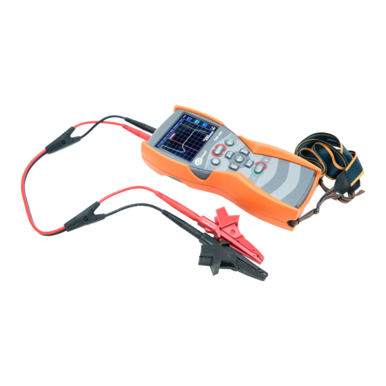
15 Accessories The kit includes: • TDR-420 Time-domain Reflectometer WMGBTDR420, • two-wire cable 0.6 m for TDR WAPRZ0X6DZBB, • red crocodile clip 1 kV 20 A WAKRORE20K02, • black crocodile clip 1 kV 20 A WAKROBL20K01, • case M6 WAFUTM6, •... -
Page 29: Laboratory Services
17 Laboratory services SONEL Testing and Calibration Laboratory has been accredited by the Polish Center of Accredi- tation for the calibration of measuring instruments AP 173 in the following field - electrical properties in DC and LF circuits: voltage and current (DC), voltage and current (AC), resistance (DC), electrical power. - Page 30 NOTES TDR-420 – USER MANUAL...
Need help?
Do you have a question about the TDR-420 and is the answer not in the manual?
Questions and answers