Table of Contents
Advertisement
Quick Links
Advertisement
Table of Contents

Summary of Contents for Sonel TDR-410
-
Page 3: Operating Manual
OPERATING MANUAL TDR-410 TDR CABLE FAULT LOCATOR SONEL S. A. Wokulskiego 11 58-100 Świdnica Poland Version 1.03 08.09.2017 TDR-410 OPERATING MANUAL version 1.03... - Page 4 We appreciate your having purchased our measuring instrument. TDR-410 is a modern measuring device, which is easy and safe to use. Please acquaint yourself with the present manual in order to avoid measuring errors and prevent possible problems related to operation of the meter.
-
Page 5: Table Of Contents
Auto Fault Location and Manual Fault Location ........10 4.1.4 Selecting range scales.................. 11 4.1.5 Gain settings ....................11 CONNECTING TDR-410 TO A CABLE TO BE TESTED ....... 11 CABLE FAULT LOCATION ................12 ..........13 CAN HOLD AND ONTINUOUS... - Page 6 ACCESSORIES ..................... 19 MANUFACTURER ....................19 TDR-410 OPERATING MANUAL version 1.03...
-
Page 7: Introduction
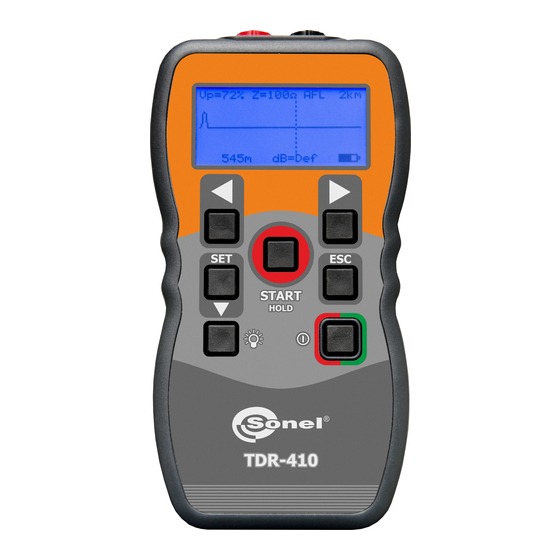
Designed for identifying and locating faults on all metallic cables with two or more insulated conduc- tors. The TDR-410 has impedance matched circuits for 25, 50, 75 and 100 ohms and with velocity of propagation settings from 1-99% (or the equivalent in feet or meters/micro second) will cover the range of power, data, communication and CCTV cables. -
Page 8: Working Principles
2 Working principles TDR-410 measures the time course of the signal (the probe pulse) in a pair from connecting the cable to the cable end or the nearest damage and back. Probe pulses in the cable run at a speed Vp (the speed of propagation), which depends on the elec- trical parameters of the cable, in particular the material from which the insulation is made. -
Page 9: Set Unit Of Measure From Menu Display
3.2 Set Auto Shutdown from menu display To preserve battery life the TDR-410 is fitted with an auto shutdown feature. Shutdown time is se- lectable between disabled 1, 2, 3 and 5 minutes. -
Page 10: Set Contrast From Menu Display
3.6 How to determine V Settings If the TDR-410 is to be used with a cable type for which the Vp is unknown, this must first be deter- mined by the setting selected in section 3.5 1. Take a sample of the cable at least 10m or 30 ft long (as long as possible). -
Page 11: Using The Tdr-410
Note: After disconnecting the TDR-410 the current parameter settings are stored, including the re- cently selected values Vp propagation factor and impedance Z. This feature of the device is particularly advantageous in situations where multiple tests are per- formed on the same type of cables. -
Page 12: Setting Velocity Of Propagation (Vp)
Auto Fault Location. When set in auto fault location (AFL) the TDR-410 will scan the cable run and the cursor will automat- ically stop at the first event. To start the scan press START key, if the scan stops within the first me- ter (3 feet) it will identified the connection between the TDR-410 and the cable under test as an event, press the key START to continue the scan. -
Page 13: Selecting Range Scales
4.1.5 Gain settings The TDR-410 has pre set gain for each of its 11 range scales, there is in addition to this a user con- trollable gain to a maximum of 64 dB in 1 dB steps. To use this function, use navigation key (SET... -
Page 14: Cable Fault Location
The vertical cursor line is moved left or right along the line of the trace by pressing buttons to determine the distance to the event. Position the cursor at the beginning of the event and read off the distance at the bottom left corner. TDR-410 OPERATING MANUAL version 1.03... -
Page 15: Scan Hold And Continuous Scanning Modes
7 Tone Generator The TDR-410 may also be used as a tone generator to trace and identify cables and wires. The user will need a conventional inductive tone probe within the range 810Hz to 1110Hz. -
Page 16: Power Supply
8 Power supply Reflectometer TDR-410 is powered by four 1.5 V AA batteries. Use alkaline batteries to ensure prop- er functioning of the device. Low battery is signaled by the appearance of the symbol on the screen of the reflectometer. -
Page 17: Typical Fault Displays
Before the equipment is sent to a collection point, do not dismantle any elements. Observe the local regulations concerning disposal of packages, worn-out batteries and accumulators. 12 Typical Fault Displays The following diagrams show typical fault traces to assist you in the identification of faults using the TDR-410: TDR-410 OPERATING MANUAL version 1.03... -
Page 18: Typical Cable V Pand Impedance Values
U/UTP cat. 6 0.67 Note: TDR-410 measures the distance to a fault in a cable or the cable length with an accuracy spec- ified in the technical specifications. The current accuracy of the measurement depends on: - how the the propagation factor V was determined, - its stability on the whole lenght of the tested cable. - Page 19 Cable type Cat 5 STP Cat 5 UTP Coaxial air 50/75 Coaxial drive 50/75 Coaxial PE foam 50/75 Coaxial full PE 50/75 Symmetrical PE gel Symmetrical dry PE Symmetrical PTFE Symmetrical PVC Paper 72nF Paper 83nF TDR-410 OPERATING MANUAL version 1.03...
-
Page 20: Technical Data
* Measurement accuracy of <+/- 1% assumes the instrument setting for velocity of propagation (Vp) of the cable under test to be accurately set, homogeneity of the Vp along the cable length, and accu- rate cursor positioning. TDR-410 OPERATING MANUAL version 1.03... - Page 21 15 Accessories The standard set provided by the manufacturer includes the following components: Time-domain reflektometer TDR-410 WMGBTDR410 0.6 m double-wire lead WAPRZ0X6DZBB, red crocodile clip WAKRORE20K02, black crocodile clip WAKROBL20K01, cover M-2 WAFUTM2, alkaline batteries 1.5V AA (4 pieces), ...
- Page 22 NOTES TDR-410 OPERATING MANUAL version 1.03...


Need help?
Do you have a question about the TDR-410 and is the answer not in the manual?
Questions and answers