Table of Contents
Advertisement
Quick Links
Advertisement
Table of Contents

Subscribe to Our Youtube Channel
Related Manuals for Best 9K Series


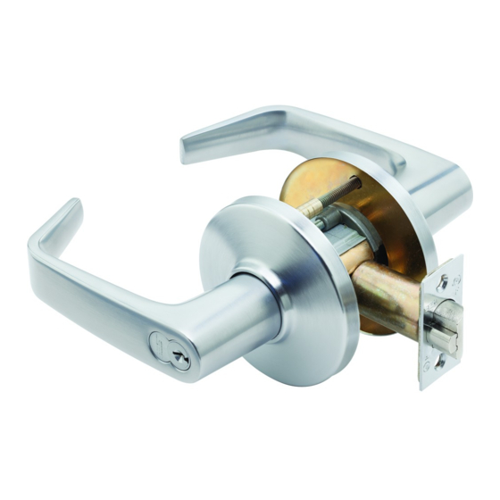
Summary of Contents for Best 9K Series
- Page 2 United States of America. Information in this document is subject to change without notice and does not represent a commitment on the part of BEST Access Solutions, Inc. The software described in this document is furnished under a license agreement or nondisclosure agreement.
-
Page 3: Table Of Contents
AB function chassis—entrance lock (ANSI F109) 2–12 C function chassis—corridor lock (ANSI F88) 2–13 D function chassis—storeroom lock (ANSI F86) 2–14 E function chassis—service station lock (ANSI F92) 2–15 G function chassis—storeroom lock (ANSI F91) 2–16 9K Series Service Manual... - Page 4 2–47 Trim parts 2–50 Standard strikes and strike boxes 2–50 Non-standard strikes 2–50 Lead-lined parts 2–51 Roses, rose liners, and rose spacers 2–52 Standard levers and components 2–54 Dummy trim 2–57 Latches 2–58 Installation tools 2–59 9K Series Service Manual...
- Page 5 3–22 Positioning the cam for C function locks 3–22 Positioning the cam for G and IN function locks 3–23 Emergency key instructions for H and HJ function locks 3–24 Troubleshooting 3–25 A–1 NSTALLATION NSTRUCTIONS B–1 NDEX 9K Series Service Manual...
- Page 6 Contents 9K Series Service Manual...
-
Page 7: Figures
3–5 Removing the outside rose and liner assembly 3–6 Replacing the outside rose and liner assembly 3–7 Removing the button assembly 3–8 Inserting the button assembly into the sleeve 3–9 Bending the button assembly tab 3–9 9K Series Service Manual... - Page 8 Correct position of the C function inside locking cam 3–22 Correct position of the G and IN function locking cam 3–23 Intermediate position of the G and IN function locking cam 3–23 Inserting the emergency key 3–24 viii 9K Series Service Manual...
-
Page 9: Getting Started
TARTED NTRODUCTION The 9K Series Service Manual contains essential information to help you maintain your 9K Series Lock. This manual addresses standard and electrified 9K Series Locks. Throughout this manual, the term electrified is used to refer to 93KW–95KW DEL, DEU function locks. -
Page 10: Certifications And Standards
■ Standards and Appeals under calendar number 730-89-SA. See CSFM listing number 4136-1175:103. Accessories The 8W599 transformer is UL listed. ■ ■ The 8WCON AC to DC converter full wave bridge rectifier is UL recognized. 1–2 9K Series Service Manual... -
Page 11: Documentation Package
Getting Started OCUMENTATION PACKAGE The following documentation is available to help you with the installation, start-up, and maintenance of your 9K Series Lock. The installation and assembly instructions also can be ordered separately: Document Title Doc. No. T56075 Installation Instructions for 9K Cylindrical Locks... -
Page 12: Technical Support
A factory-trained Certified Product Specialist (CPS) is available in your technical area whenever you need help. Before you call, however, please make sure you are where the 9K Series Lock is, and that you are prepared to support give the following information: what happened and what you were doing when the question arose ■... - Page 13 UNCTIONS AND ARTS ISTS The following pages contain function descriptions for all 9K Series Locks. This chapter also includes exploded diagrams that show all field serviceable mechanical parts, diagrams of trim and other miscellaneous parts, and function conversion information. 9K Series Service Manual...
-
Page 14: Functions And Parts Lists
(page 2–8) ■ ■ electrified (page 2–11). For a list of the BEST designation for each ANSI-defined function, see page 2–11. Note: If the function is ANSI defined, the ANSI designation appears by the function name. Latch Shading indicates that the lever is fixed. -
Page 15: Single-Keyed Functions
“Occupied” indicator in the outside lever ■ inside button is pushed in but and blocks all operating keys. For the HJ function, not rotated pushing the inside button blocks all operating keys. Inside lever is always unlocked 9K Series Service Manual 2–3... - Page 16 ■ inside lever when the inside ■ Inside lever is always button is pushed in unlocked outside key ■ closing the door when the ■ inside button is pushed in Inside lever is always unlocked 2–4 9K Series Service Manual...
-
Page 17: Double-Keyed Functions
■ ■ Inside lever locked by: Inside lever is always unlocked inside key ■ Inside lever unlocked by: inside key ■ Note: Turning the key in either lever locks or unlocks that lever independently. 9K Series Service Manual 2–5... - Page 18 Functions and Parts Lists W–Institutional (ANSI F87) Latchbolt operated by: inside key ■ outside key ■ Outside lever is always fixed Inside lever is always fixed 2–6 9K Series Service Manual...
-
Page 19: Non-Keyed Functions
■ door or a non-latching door. Inside lever is always unlocked 2DT–Double dummy trim This lock is a through-bolt mounted pair of matching levers for an inactive door or a non-latching door. 9K Series Service Manual 2–7... -
Page 20: Special Functions
Outside lever unlocked by: inside lever ■ inside button when rotated ■ counterclockwise outside key ■ Inside lever is always unlocked Note: Turning the slotted button keeps the outside lever locked until the button is turned back. 2–8 9K Series Service Manual... - Page 21 ■ Outside lever unlocked by: inside lever ■ outside key outside button when pushed ■ ■ Inside lever is always fixed in and rotated counterclockwise closing the door ■ Inside lever is always unlocked 9K Series Service Manual 2–9...
- Page 22 Note: Do not use this function for rooms that have no other entrance. Z–Closet latch Latchbolt operated by: inside turn knob ■ outside lever ■ Outside lever is always unlocked Inside turn knob is always unlocked 2–10 9K Series Service Manual...
-
Page 23: Electrified Cylindrical Functions
24 VDC from the ■ only while power continues solenoid to be applied Inside lever is always Inside lever is always unlocked unlocked Functions ANSI no. Function by ANSI designation F109 9K Series Service Manual 2–11... -
Page 24: Standard Functions
TANDARD FUNCTIONS — (ANSI F109) FUNCTION CHASSIS ENTRANCE LOCK Item Part No. Qty. Description B55692 Turn button assembly A55685 Inside hub and locking pin assembly B55610 Non-keyed sleeve and driver assembly B55518 Lever return spring B55504 Thrust plate B54172 Chassis cover B54886 Retractor assembly with long catchplate A55673... -
Page 25: C Function Chassis-Corridor Lock (Ansi F88)
— (ANSI F88) FUNCTION CHASSIS CORRIDOR LOCK Item Part No. Qty. Description A55685 Inside hub and locking pin assembly or not shown A56008 Inside hub assembly, lost motion B55700 Sleeve & key release cam assembly or not shown B56024 Sleeve & key release cam assembly not shown B89839 Sleeve &... -
Page 26: D Function Chassis-Storeroom Lock (Ansi F86)
— (ANSI F86) FUNCTION CHASSIS STOREROOM LOCK Item Part No. Qty. Description A55685 Inside hub and locking pin assembly B55610 Non-keyed sleeve and driver assembly B55518 Lever return spring B55504 Thrust plate B54172 Chassis cover B54888 Retractor assembly without catchplate A55675 Key release cam assembly C55515... -
Page 27: E Function Chassis-Service Station Lock (Ansi F92)
— (ANSI F92) FUNCTION CHASSIS SERVICE STATION LOCK Item Part No. Qty. Description B55694 Slotted button assembly A55685 Inside hub and locking pin assembly B55610 Non-keyed sleeve and driver assembly B55518 Lever return spring B55504 Thrust plate B54172 Chassis cover B54886 Retractor assembly with long catchplate A55673... -
Page 28: G Function Chassis-Storeroom Lock (Ansi F91)
— (ANSI F91) FUNCTION CHASSIS STOREROOM LOCK Item Part No. Qty. Description A55685 Inside hub and locking pin assembly or not shown A56008 Inside hub assembly, lost motion Keyed sleeve assembly or A55687 not shown A55725 Keyed sleeve assembly Keyed sleeve assembly not shown A88631 C55515... -
Page 29: H Function Chassis-Hotel Guest Room Lock With Indicator (Ansi F93)
— (ANSI F93) FUNCTION CHASSIS HOTEL GUEST ROOM LOCK WITH INDICATOR — FUNCTION CHASSIS HOTEL GUEST ROOM LOCK WITHOUT INDICATOR Item Part No. Qty. Description B55693 Push button assembly A55685 Inside hub and locking pin assembly B55610 Non-keyed sleeve and driver assembly B55518 Lever return spring B55504... -
Page 30: L Function Chassis-Privacy Lock (Ansi F76)
— (ANSI F76) FUNCTION CHASSIS PRIVACY LOCK Item Part No. Qty. Description B55693 Push button assembly A55685 Inside hub and locking pin assembly B55610 Non-keyed sleeve and driver assembly B55518 Lever return spring B55504 Thrust plate B54172 Chassis cover B54886 Retractor assembly with long catchplate A55673 Key release cam assembly... -
Page 31: N Function Chassis-Passage Lock (Ansi F75)
— (ANSI F75) FUNCTION CHASSIS PASSAGE LOCK Item Part No. Qty. Description A55685 Inside hub and locking pin assembly B55610 Non-keyed sleeve and driver assembly B55518 Lever return spring B55504 Thrust plate B54172 Chassis cover B54888 Retractor assembly without catchplate D55571 Outside hub A55505... -
Page 32: Nx Function Chassis-Exit Lock (Ansi F89)
— (ANSI F89) FUNCTION CHASSIS EXIT LOCK Item Part No. Qty. Description B55690 Locking bar assembly for “NX” function A55685 Inside hub and locking pin assembly B55610 Non-keyed sleeve and driver assembly B55518 Lever return spring B55504 Thrust plate B54172 Chassis cover B54888 Retractor assembly without catchplate... -
Page 33: P Function Chassis-Patio Lock (Ansi F77)
— (ANSI F77) FUNCTION CHASSIS PATIO LOCK Item Part No. Qty. Description B55693 Push button assembly A55685 Inside hub and locking pin assembly B55610 Non-keyed sleeve and driver assembly B55518 Lever return spring B55504 Thrust plate B54172 Chassis cover B54886 Retractor assembly with long catchplate A55680 Key release cam assembly... -
Page 34: R Function Chassis-Classroom Lock (Ansi F84)
— (ANSI F84) FUNCTION CHASSIS CLASSROOM LOCK Item Part No. Qty. Description A55685 Inside hub and locking pin assembly B55610 Non-keyed sleeve and driver assembly B55518 Lever return spring B55504 Thrust plate B54172 Chassis cover B54888 Retractor assembly without catchplate A55681 Key release cam assembly C55515... -
Page 35: S Function Chassis-Communicating Lock (Ansi F80)
— (ANSI F80) FUNCTION CHASSIS COMMUNICATING LOCK Item Part No. Qty. Description A55685 Inside hub and locking pin assembly or not shown A56008 Inside hub assembly, lost motion A55687 Keyed sleeve assembly or not shown A55725 Keyed sleeve assembly not shown A88631 Keyed sleeve assembly C55515... -
Page 36: T Function Chassis-Dormitory Lock (Ansi F90)
— (ANSI F90) FUNCTION CHASSIS DORMITORY LOCK Item Part No. Qty. Description B55693 Push button assembly A55685 Inside hub and locking pin assembly B55610 Non-keyed sleeve and driver assembly B55518 Lever return spring B55504 Thrust plate B54172 Chassis cover B54886 Retractor assembly with long catchplate A55681 Key release cam assembly... -
Page 37: W Function Chassis-Utility Or Institutional Lock (Ansi F87)
— (ANSI F87) FUNCTION CHASSIS UTILITY OR INSTITUTIONAL LOCK Item Part No. Qty. Description A55685 Inside hub and locking pin assembly or not shown A56008 Inside hub assembly, lost motion A55687 Keyed sleeve assembly or Keyed sleeve assembly not shown A55725 Keyed sleeve assembly not shown... -
Page 38: Y Function Chassis-Exit Lock
— FUNCTION CHASSIS EXIT LOCK Item Part No. Qty. Description A55685 Inside hub and locking pin assembly B55610 Non-keyed sleeve and driver assembly B55518 Lever return spring B55504 Thrust plate B54172 Chassis cover B54888 Retractor assembly without catchplate B54809 Outside hub and plate assembly A55511 Chassis screw Outside... -
Page 39: Non-Standard Functions
STANDARD FUNCTIONS — (ANSI F81) FUNCTION CHASSIS ENTRANCE LOCK Item Part No. Qty. Description B55692 Turn button assembly A55685 Inside hub and locking pin assembly B55610 Non-keyed sleeve and driver assembly B55518 Lever return spring B55504 Thrust plate B54172 Chassis cover B54888 Retractor assembly without catchplate A55673... -
Page 40: B Function Chassis-Office Lock (Ansi F82)
— (ANSI F82) FUNCTION CHASSIS OFFICE LOCK Item Part No. Qty. Description B55693 Push button assembly A55685 Inside hub and locking pin assembly B55610 Non-keyed sleeve and driver assembly B55518 Lever return spring B55504 Thrust plate B54172 Chassis cover B54887 Retractor assembly with short catchplate A55673 Key release cam assembly... -
Page 41: Dr Function Chassis-Special Lock
— FUNCTION CHASSIS SPECIAL LOCK Item Part No. Qty. Description A55685 Inside hub, and locking pin assembly or not shown A56008 Inside hub assembly, lost motion Keyed A55687 sleeve assembly or Keyed sleeve assembly not shown A55725 not shown A88631 Keyed sleeve assembly C55515 Spring drive plate... - Page 42 — FUNCTION CHASSIS CLOSET OR STOREROOM LOCK Item Part No. Qty. Description A54736 Turn blade assembly for Z function B54810 Inside hub and side plate assembly A54835 Non-keyed sleeve and driver assembly B54172 Chassis cover B54888 Retractor assembly without catchplate A55675 Key release cam assembly B55504...
-
Page 43: Ea Function Chassis-Entrance Or Office Lock
— FUNCTION CHASSIS ENTRANCE OR OFFICE LOCK Item Part No. Qty. Description B55694 Slotted button assembly A55685 Inside hub and locking pin assembly B55610 Non-keyed sleeve and driver assembly B55518 Lever return spring B55504 Thrust plate B54172 Chassis cover B54887 Retractor assembly with short catchplate A55673 Key release cam assembly... - Page 44 — FUNCTION CHASSIS INTRUDER LOCK Item Part No. Qty. Description A55685 Inside hub and locking pin assembly or not shown A56008 Inside hub and locking pin assembly, lost motion A55687 Keyed sleeve assembly or not shown A55725 Keyed sleeve assembly not shown A88631 Keyed sleeve assembly...
-
Page 45: Ll Function Chassis-Hospital Privacy Lock
— FUNCTION CHASSIS HOSPITAL PRIVACY LOCK Item Part No. Qty. Description B55693 Push button assembly A55685 Inside hub and locking pin assembly B55610 Non-keyed sleeve and driver assembly B55518 Lever return spring B55504 Thrust plate B54172 Chassis cover B54886 Retractor assembly with long catchplate A55673 Key release cam assembly C55515... -
Page 46: M Function Chassis-Communicating Lock (Ansi F78)
— (ANSI F78) FUNCTION CHASSIS COMMUNICATING LOCK Item Part No. Qty. Description A55695 Turn button assembly A55685 Inside hub and locking pin assembly Inside hub and locking pin assembly, lost motion not shown A56008 B55610 Non-keyed sleeve and driver assembly B55518 Lever return spring B55504... -
Page 47: Q Function Chassis-Exit Lock (Ansi F83)
— (ANSI F83) FUNCTION CHASSIS EXIT LOCK Item Part No. Qty. Description B55692 Turn button assembly A55685 Inside hub and locking pin assembly B55610 Non-keyed sleeve and driver assembly B55518 Lever return spring B55504 Thrust plate B54172 Chassis cover B54888 Retractor assembly without catchplate A55680 Key release cam assembly... -
Page 48: Rd Function Chassis-Special Lock
— FUNCTION CHASSIS SPECIAL LOCK Item Part No. Qty. Description A55685 Inside hub and locking pin assembly or not shown A56008 Inside hub assembly, lost motion A55687 Keyed sleeve assembly or Keyed sleeve assembly not shown A55725 not shown A88631 Keyed sleeve assembly C55515 Spring drive plate... -
Page 49: Rz Function Chassis-Closet Or Storeroom Lock
— FUNCTION CHASSIS CLOSET OR STOREROOM LOCK Item Part No. Qty. Description A54736 Turn blade assembly for Z function A54810 Inside hub and side plate assembly A54835 Non-keyed sleeve and driver assembly B54172 Chassis cover B54888 Retractor assembly without catchplate B55681 Key release cam assembly B55504... -
Page 50: Xd Function Chassis-Special Lock
— FUNCTION CHASSIS SPECIAL LOCK Item Part No. Qty. Description A55685 Inside hub and locking pin assembly or not shown A56008 Inside hub assembly, lost motion A55687 Keyed sleeve assembly or Keyed sleeve assembly not shown A55725 Keyed sleeve assembly not shown A88631 C55515... -
Page 51: Xr Function Chassis-Special Lock
— FUNCTION CHASSIS SPECIAL LOCK Item Part No. Qty. Description A55685 Inside hub and locking pin assembly or not shown A56008 Inside hub assembly, lost motion A55687 Keyed sleeve assembly or Keyed sleeve assembly not shown A55725 not shown A88631 Keyed sleeve assembly C55515 Spring drive plate... - Page 52 — FUNCTION CHASSIS EXIT LOCK Item Part No. Qty. Description A55685 Inside hub and locking pin assembly or not shown A56008 Inside hub assembly, lost motion A55687 Keyed sleeve assembly or Keyed sleeve assembly not shown A55725 not shown A88631 Keyed sleeve assembly C55515 Spring drive plate...
-
Page 53: Yr Function Chassis-Special Lock
— FUNCTION CHASSIS SPECIAL LOCK Item Part No. Qty. Description A55685 Inside hub and locking pin assembly or not shown A56008 Inside hub assembly, lost motion A55687 Keyed sleeve assembly or Keyed sleeve assembly not shown A55725 not shown A88631 Keyed sleeve assembly C55515 Spring drive plate... -
Page 54: Z Function Chassis-Closet Lock
— FUNCTION CHASSIS CLOSET LOCK Item Part No. Qty. Description A54736 Turn blade assembly for Z function A54810 Inside hub and side plate assembly A54835 Non-keyed sleeve and driver assembly B54172 Chassis cover B54888 Retractor assembly without catchplate B55504 Thrust plate B55518 Lever return spring A55610... -
Page 55: Electrified Functions
LECTRIFIED FUNCTIONS — FUNCTION CHASSIS ELECTRICALLY LOCKED FAIL SAFE Outside Inside Figure 2.33 DEL function exploded diagram... - Page 56 1 Keyed sleeve assembly D55571 1 Outside hub or not shown D56003 1 Outside hub, lost motion A55505 2 Chassis screw a. For use with non-interchangeable cores. b. For use with large format interchangeable cores. 2–44 9K Series Service Manual...
-
Page 57: Deu Function Chassis-Electrically Unlocked Fail Safe
— FUNCTION CHASSIS ELECTRICALLY UNLOCKED FAIL SAFE Outside Inside Figure 2.34 DEU function exploded diagram... - Page 58 1 Keyed sleeve assembly D55571 1 Outside hub or not shown D56003 1 Outside hub, lost motion A55505 2 Chassis screw a. For use with non-interchangeable cores. b. For use with large format interchangeable cores. 2–46 9K Series Service Manual...
-
Page 59: Function Conversion
If you want to convert the function of an existing 9K Lock, use the following tables to determine the internal parts that you need. Unless otherwise noted, a quantity of one is used for each part. 9K Series Service Manual 2–47... - Page 60 For the non-IC function, use in place of the keyed sleeve assembly, A55687. e. For the non-IC function, use in place of the sleeve & key release cam assembly, B55700. f. Use a quantity of one (1). 2–48 9K Series Service Manual...
- Page 61 For the non-interchangeable function, use in place of the keyed sleeve and driver assembly, A55687. f. For the large format interchangeable function, use in place of the keyed sleeve and driver assembly, A55687. g. Use a quantity of one (1). 9K Series Service Manual 2–49...
-
Page 62: Trim Parts
2″ B54069 2 1/4″ B54070 2 1/2″ The measurement is taken from the edge B54072 4″ of the lip to the center of the screw holes. a. Specify finish. Figure 2.36 Understanding strike lip measurement 2–50 9K Series Service Manual... -
Page 63: Lead-Lined Parts
Figure 2.37 Cross-section of 9K locks showing lead-lined parts Lead-lined parts list Item Description Turn button liner with shield Inside lever sleeve with shield (for button levers) Hub and side plate with shield Inside lever sleeve with shield (for plain levers) 9K Series Service Manual 2–51... -
Page 64: Roses, Rose Liners, And Rose Spacers
Roses, rose liners, and rose spacers Style C Style D Style K Style L Small spacer Large spacer Y function Small RQE rose liner Large RQE rose liner Figure 2.38 Roses, rose liners, and rose spacers 2–52 9K Series Service Manual... - Page 65 ATB2 Large inside rose and liner assembly not shown B88638 ATB2 Large outside rose and liner assembly 9 & 11 B55606 Large inside rose and liner assembly 10 & 11 B55600 Large outside rose and liner assembly 9K Series Service Manual 2–53...
-
Page 66: Standard Levers And Components
D8862 D88628 D55023 Keyed lever Corbin Russwin LFIC Lever not shown Keyed lever for H functions D8862 D88629 B55110 not shown not shown D80992 Universal lever for use with non-interchangeable cores 2–54 9K Series Service Manual... -
Page 67: Lever Components With Interchangeable Cores
For information about cores and keys, see the Core and Key Service Manual. Figure 2.41 Lever components with interchangeable cores Lever components with interchangeable cores parts list Item Part no. Qty. Description A88633 Yale tailpiece A88634 Yale six pin spacer B88756 Schlage tailpiece 9K Series Service Manual 2–55... -
Page 68: Lever Components For Use With Non-Interchangeable Cores
1888798 Non-interchangeable cylinder, zero-bitted a. The throw members shipped with non-interchangeable cylinders are incompatible with 9K Series Locks. Refer to Lever components for use with non-interchangeable cores parts list above to select the appropriate throw member. b. Contains a set of 4 cylinders. -
Page 69: Dummy Trim
Item Part No. Qty. Description B55239 Chassis sub-assembly A54465 “O” ring B55051 Small liner and ring assembly or B55050 Large liner and ring assembly B55067 Chassis sub-assembly A18991 #8-32 × 1 1/8 Phil. FHMS screw 9K Series Service Manual 2–57... -
Page 70: Latches
2 3/4″ A54661 Latch with 3/4″ throw Deadlocking 3 3/4″ C54682 8KL4 Latch Deadlocking 5″ C54684 8KL5 Latch Spring 2 3/4″ C54681 8KSL3 Latch Spring 3 3/4″ C54683 8KSL4 Latch Spring 5″ C54685 8KSL5 Latch 2–58 9K Series Service Manual... -
Page 71: Installation Tools
Functions and Parts Lists Installation tools Figure 2.45 Installation tools Installation tools parts list Nomen- Item clature Part no. Description KD303 C55034 Drill jig KD325 A01514 Strike plate locating pin KD315 1350393 Faceplate marking chisel 9K Series Service Manual 2–59... - Page 72 2 1/8″ diameter chassis hole bit assembly KD318 A54085 1″ diameter drill bit assembly Adaptor for 3/8″ drill chuck 1–6 KD304A N/A Boring jig kit a. Can only be ordered as part of the KD304A boring jig kit. 2–60 9K Series Service Manual...
-
Page 73: Service And Maintenance
Position the locking cam for C function locks 3–22 Position the locking cam for G and IN function locks 3–23 Use the emergency key for H and HJ function locks 3–24 Troubleshoot common problems 3–25 9K Series Service Manual 3–1... -
Page 74: Maintenance Tools
Figure 3.1 Maintenance tools Maintenance tools parts list Nomen- Item clature Part no. Description KD340 Spring loading tool KD317 C55506 Spanner wrench A25586 Emergency driver a. For use with hotel function locks (H and HJ). 3–2 9K Series Service Manual... -
Page 75: Replacing Parts
Removing the plain lever or button lever To reinstall the lever: 1. Position the lever so that the handle points toward the door hinges. 2. Slide the lever onto the sleeve and firmly push on the lever until it is seated. 9K Series Service Manual 3–3... -
Page 76: Replacing The Inside Rose And Rose Liner
2. Insert the solid, curved end of the spanner wrench in between the rose and the sleeve, as shown in Figure 3.5. Pry the rose until it pops off of the liner. Inside rose Spanner wrench Sleeve Figure 3.5 Removing the inside rose with the spanner wrench 3–4 9K Series Service Manual... -
Page 77: Replacing The Inside Rose And Rose Liner
4. If there is an RQE rose liner, connect it. 5. Install the rose. 6. Reinstall the lever. See page 3–3 Rose liner Through-bolt Rose Through-bolt Figure 3.7 Replacing the inside rose and rose liner 9K Series Service Manual 3–5... -
Page 78: Replacing The Outside Rose And Liner Assembly
Retractor-side view of the chassis Rose and liner assembly Retractor Rose locking pin Head-on view of the rose and liner assembly from the inside sleeve side Figure 3.8 Removing the outside rose and liner assembly 3–6 9K Series Service Manual... -
Page 79: Replacing The Rqe Rose Liner For Electrified Locks
Caution 2. Install the through-bolts through the RQE rose liner and door in the top and bottom holes. 3. Tighten the RQE rose liner on the door with the through-bolts. 4. Connect the RQE connector. 9K Series Service Manual 3–7... -
Page 80: Replacing The Button Assembly
The tab should now lie flat. Note: When performing this step, it is best to position the lock on a flat surface so that the retractor faces upward. 3. Press down on the retractor and slide the button assembly out of the sleeve. - Page 81 Do not bend the tab so that it protrudes further than the diameter of the sleeve. It could interfere with the lever function. Sleeve Button assembly Button assembly tab Figure 3.12 Bending the button assembly tab 9K Series Service Manual 3–9...
-
Page 82: Replacing The Lever Keeper Spring
Figure 3.13 Removing the lever keeper spring To reinstall the lever keeper spring: 1. Position the lever keeper spring as shown in Figure 3.14. Sleeve Lever keeper spring Figure 3.14 Positioning the lever keeper spring 3–10 9K Series Service Manual... -
Page 83: Replacing The Lever Return Spring
Caution 1. Remove the following components: ■ levers (page 3–3) roses and rose liners (page 3–4 page 3–6) ■ button assembly, if present (page 3–8). ■ 9K Series Service Manual 3–11... -
Page 84: Removing The Lever Return Spring
4. Pull the end of the lever return spring up and over the raised edge on the spring drive plate or non-keyed sleeve. See Figure 3.18. Raised edge on the spring drive plate Lever return spring Figure 3.18 Removing the lever return spring 3–12 9K Series Service Manual... -
Page 85: Positioning The Lever Return Spring
Figure 3.20. Note: Make sure that the lever return spring does not separate and ride onto the top of the sleeve. 9K Series Service Manual 3–13... -
Page 86: Positioning The Retractor Assembly
Foot of the retractor assembly assembly Notch in the inside hub Notch in the inside hub Ear on the key release Ear on the key release cam assembly cam assembly Figure 3.22 Positioning the retractor assembly 3–14 9K Series Service Manual... -
Page 87: Replacing The Key Release Cam Assembly
(page 3–8) lever return spring (page 3–11). ■ 2. Pull the key release cam assembly out of the sleeve. Sleeve Key release cam assembly Figure 3.24 Removing the key release cam assembly 9K Series Service Manual 3–15... -
Page 88: Replacing The Spring Drive Plate
(page 3–11) key release cam assembly (page 3–15). ■ 2. Pull the spring drive plate out of the hub, as shown in Figure 3.26. Spring drive plate Figure 3.26 Removing the spring drive plate 3–16 9K Series Service Manual... -
Page 89: Replacing The Sleeve Assembly
(page 3–4 page 3–6) ■ button assembly, if present (page 3–8) ■ ■ lever return spring (page 3–11) key release cam assembly (page 3–15) ■ spring drive plate (page 3–16). ■ 9K Series Service Manual 3–17... -
Page 90: Replacing The Sleeve Assembly
2. Insert a flat blade screwdriver through the sleeve and into the lever keeper. 3. Press the screwdriver blade in the direction of the arrow in Figure 3.30. Push the sleeve the rest of the way through the hub. Sleeve Figure 3.30 Replacing the sleeve assembly 3–18 9K Series Service Manual... -
Page 91: Replacing The Solenoid For Electified Locks
(page 3–3). ■ Replacing the Because of the complex nature of this procedure, BEST recommends solenoid for that you order a new cylindrical chassis. Contact your BEST representative. electified locks Use the part numbers listed in Reversing the solenoid when changing the function when ordering a new cylindrical chassis. -
Page 92: Reversing The Solenoid When Changing The Function
Service and Maintenance EVERSING THE SOLENOID WHEN CHANGING THE FUNCTION Because of the complex nature of this procedure, BEST recommends that you order a new electrified function chassis. Contact your BEST representative. Use the following part numbers when ordering a new eletrified function chassis. -
Page 93: Aligning The Chassis And Trim
Figure 3.32 Engaging the retractor in the latch 3. Tighten the chassis screws. 4. Test the lever operation to make sure that the latch tailpiece does not bind with the chassis retractor. 5. Reinstall the inside trim. See page 3–5 for instructions. 9K Series Service Manual 3–21... -
Page 94: Cam Positioning Instructions
2. Install the core and throw member. 3. Check the operation of the levers while the door is open. The outside lever is locked by rotating the inside key 360° counterclockwise and unlocked by rotating the inside key 360° clockwise. 3–22 9K Series Service Manual... -
Page 95: Positioning The Cam For G And In Function Locks
5. Reinstall that lever’s core and throw member. 6. Check the operation of the levers while the door is open. The levers are locked by rotating the key 1 1/4 turns counterclockwise and unlocked by rotating the key 1 1/4 turns clockwise. 9K Series Service Manual 3–23... - Page 96 1. Remove the core and the throw member. 2. Insert the blade of the emergency key into the slot, as shown in Figure 3.36. Slot Emergency key Figure 3.36 Inserting the emergency key 3. Turn the key and retract the latch. 3–24 9K Series Service Manual...
-
Page 97: Troubleshooting
Cannot remove the operating key Key is turned 180° past the correct Push the inside button, turn the key from an H or HJ function lock. position. back clockwise 180°, and remove the key. 9K Series Service Manual 3–25... - Page 98 Service and Maintenance 3–26 9K Series Service Manual...
-
Page 99: Installation Instructions
NSTALLATION NSTRUCTIONS The following pages contain the Installation Instructions for 9K Cylindrical Locks and the Wiring Instructions for 8K & 9K Series Electrified Cylindrical Locks. 9K Series Service Manual A–1... - Page 100 Installation Instructions A–2 9K Series Service Manual...
- Page 101 40 5/16". If steel frames are used, the latch centerline must be in line with the center of the strike preparation. ■ Pull the rose locking pin and rotate the outside rose liner in or out —Continued BEST ACCESS SYSTEMS T56075/Rev B 1798029 ER-7991-19 May 2003 Indianapolis, Indiana...
- Page 102 (see Figure 8, bottom). 4 Turn the key 15 degrees counterclockwise and remove the key. Caution: Since the control key is a high-security key, make sure to keep it protected. BEST ACCESS SYSTEMS T56075/Rev B 1798029 ER-7991-19 May 2003 Indianapolis, Indiana...
- Page 103 Wiring Instructions for 8K and 9K Series Electrified Cylindrical Locks with Request-to-exit Wiring diagram The diagram below shows how to wire 8K and 9K electrified locks. 8WCON AC to DC 24 volts AC converter 8W599 60 Hz. in Transformer 24 volts DC 60 Hz.
- Page 104 = 18 volt-amps Choose a transformer with a rating of at least: (4.32 volt-amps + 18 volt-amps) × 1 ½ = 33.48 volt-amps BEST ACCESS SYSTEMS T56090/Rev A 1800760 ER-7991-19 Mar 2000 Indianapolis, Indiana...
-
Page 105: Index
2–12, 2–27, 2–35 function description for 2–11 button bar assembly diagrams, exploded reinstalling 3–9 see part numbers and drawings removing 3–8 disassembling the lock chassis 3–12 documentation package 1–3 double dummy trim 2–7, 2–57 9K Series Service Manual... - Page 106 L chassis 2–7 aligning 3–21 inside hub and locking pin for LL chassis 2–9 disassembling 3–12 assembly, lost motion for M chassis 2–10 reassembling 3–14 2–32 for N chassis 2–7 reinstalling in the door 3–7 9K Series Service Manual...
- Page 107 D chassis 2–14 reassembling the lock chassis 3–14 single dummy trim 2–7, 2–57 for double dummy trim 2–57 reinstalling for DR chassis 2–29 button bar assembly 3–9 for DZ chassis 2–30 inside rose and rose liner 3–5 9K Series Service Manual...
- Page 108 2–49 support, technical 1–4 function description for 2–9 part numbers and drawings for 2–40 YR chassis T chassis function conversion for 2–49 function conversion for 2–48 function description for 2–9 function description for 2–4 9K Series Service Manual...
Need help?
Do you have a question about the 9K Series and is the answer not in the manual?
Questions and answers