Table of Contents
Advertisement
Quick Links
Advertisement
Table of Contents

Related Manuals for Best 7KC Series


Summary of Contents for Best 7KC Series
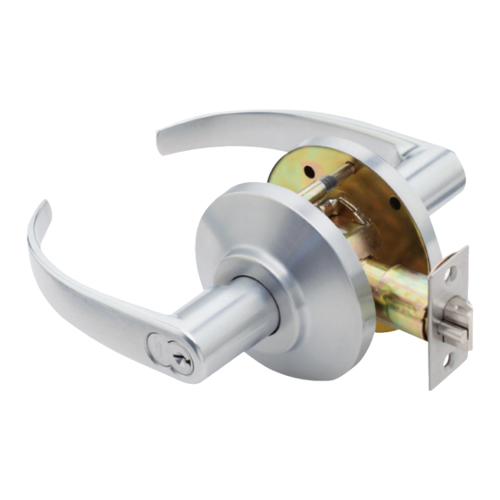
- Page 1 7KC SERIES S E R V I C E M A N U A L 7KC GRADE 2 CYLINDRICAL LOCKS...
- Page 2 REDITS OPYRIGHT Copyright ©2021 dormakaba USA Inc. All rights reserved. Information in this document is subject to change without notice and does not represent a commitment on the part of dormakaba USA Inc. The software described in this document are furnished under a license agreement or nondisclosure agreement.
-
Page 3: Table Of Contents
AB function chassis and trim—entrance lock (ANSI F109) 2–4 Trim parts 2–5 Strikes and strike boxes 2–5 Roses 2–6 Buttons 2–6 Standard levers and throw member 2–7 Non-interchangeable lever and cylinders 2–8 Latches 2–9 Installation tools 2–10 7KC Series Service Manual... - Page 4 Install boring jig and drill two 5/16” diameter holes 1–3 Adjust lock to door thickness 1–3 Engage retractor in latch 1–4 Install liner, rose, and lever 1–4 Install strike plate 1–4 Install core 1–4 B–1 NDEX 7KC Series Service Manual...
- Page 5 3–7 Engaging the retractor in the latch 3–8 Removing the button assembly 3–9 Inserting the button assembly into the sleeve 3–9 Engaging the retractor in the latch 3–11 Adjusting the outside rose and liner assembly 3–12 7KC Series Service Manual...
- Page 6 Figures 7KC Series Service Manual...
-
Page 7: Introduction
ETTING TARTED NTRODUCTION The 7KC Series Service Manual contains essential information to help you maintain your 7KC Series Lock. ERTIFICATIONS AND STANDARDS The product complies with ANSI A156.2, ■ Series 4000 Grade 2 standards; California Administrative Code Title 19 and Title 24; Illinois Accessibility Standard. -
Page 8: Documentation Package
Getting Started OCUMENTATION PACKAGE The following documentation is available to help you with the installation, start-up, and maintenance of your 7KC Series Lock. The installation and assembly instructions also can be ordered separately: Doc. Document Title T80622 † Installation Instructions for 72KC–75KC Cylindrical Locks Installation Instructions for 72KC–75KC OEM Key-in-Knob cylinders... -
Page 9: Technical Support
A factory-trained Certified Product Specialist (CPS) is available in your technical area whenever you need help. Before you call, however, please make sure you are where the 7KC Series Lock is, and that you are prepared to support give the following information: what happened and what you were doing when the problem arose ■... - Page 10 Getting Started 7KC Series Service Manual 1–4...
-
Page 11: Functions And Parts Lists
UNCTIONS AND ARTS ISTS The following pages contain function descriptions for all 7KC Series Locks. This chapter also includes an exploded diagram of a lock as well as diagrams of trim and other miscellaneous parts. 7KC Series Service Manual 2–1... -
Page 12: Function Descriptions
■ button pushed in but not turned outside key when inside ■ button pushed in but not turned closing door when inside ■ button pushed in but not turned Inside lever is always unlocked 7KC Series Service Manual 2–2... -
Page 13: Non-Keyed Functions
Inside lever is always unlocked non-latching door. It can be installed on either the inside or outside of the door. Functions ANSI no. Function by ANSI designation F109 7KC Series Service Manual 2–3... -
Page 14: Ab Function Chassis And Trim-Entrance Lock (Ansi F109)
— (ANSI F109) FUNCTION CHASSIS AND TRIM ENTRANCE LOCK This diagram shows the AB function lock. The chassis without trim and individual chassis parts are not available to order. See the following pages for part numbers. For levers, see page 2–7. -
Page 15: Trim Parts
Strike screw †† A53773 ANSI strike A18724 Strike screw † Specify finish. ‡ Includes one A53761 strike, two A25359 strike screws, and one B25640 strike box. †† Includes one A53773 strike and two A18724 strike screws. 7KC Series Service Manual 2–5... -
Page 16: Roses
Buttons parts list Item 1 Item 2 Item 3 Finish Turn button assembly Slotted button assembly Push button assembly 1836205 1835725 1835966 1836247 1835767 1836006 1836289 1835809 1836048 1836320 1835840 1836080 1836362 1835882 1836121 1836404 1835924 1836163 7KC Series Service Manual 2–6... -
Page 17: Standard Levers And Throw Member
D56157 Button lever handle D56158 Keyed lever handle D56155 Plain lever handle D56153 Button lever handle D56154 Keyed lever handle D56162 Plain lever handle D56160 Button lever handle D56161 Keyed lever handle † Specify finish. 7KC Series Service Manual 2–7... -
Page 18: Non-Interchangeable Lever And Cylinders
Non-interchangeable cylinder, keyed alike not shown 1891329 ‡ not shown 1891287 Non-interchangeable cylinder, keyed alike not shown 1888756 Non-interchangeable cylinder, zero-bitted not shown 1888798 Non-interchangeable cylinder, zero-bitted † Specify finish. ‡ Contains a set of 4 cylinders. 7KC Series Service Manual 2–8... -
Page 19: Latches
B80197 5″ 6KL5-WF Deadlocking latch with wide face (1 1/8″ ) A80192 6KL2-L8 2 3/8″ Drive-in latch A80193 6KL3-L8 2 3/4″ Drive-in latch † Specify finish. ‡ Includes the latch and two A25359 latch screws. 7KC Series Service Manual 2–9... -
Page 20: Installation Tools
1487975 Faceplate marking chisel (1″ × 2 1/4″ ) A25341 Knob keeper tool † KD309 A54084 2 1/8″ diameter chassis hole bit assembly † KD318 A54085 1″ diameter drill bit assembly † Use with the boring jig. 7KC Series Service Manual 2–10... - Page 21 2 1/8″ diameter chassis hole bit assembly KD318 A54085 1″ diameter drill bit assembly † 1–6 Adaptor for 3/8″ drill chuck KD304A N/A Boring jig kit † Can only be ordered as part of the KD304A boring jig kit. 7KC Series Service Manual 2–11...
- Page 22 Functions and Parts Lists 7KC Series Service Manual 2–12...
-
Page 23: Service And Maintenance
This chapter contains instructions for replacing components, servicing and maintaining components, and troubleshooting common problems. page Replace levers 3–2 Replace roses 3–5 Replace button assemblies 3–8 Lubricate cores 3–10 Align chassis and trim 3–11 Troubleshoot common problems 3–12 7KC Series Service Manual 3–1... -
Page 24: Replacing Parts
EPLACING PARTS Replacing the lever To remove the keyed lever: For instructions regarding non-IC levers, see BEST Installation Note: Instructions for 7KC Non-IC Cores and Throw Members (T80628). 1. Insert the control key into the core and rotate the key 15 degrees to the right. -
Page 25: Removing The Plain Lever Or Button Lever
1. Insert the knob keeper tool into the hole on the shaft of the lever, as shown in Figure 3.2. 2. Slide the lever off the sleeve. Knob keeper tool Inside of door Figure 3.2 Removing the plain lever or button lever 7KC Series Service Manual 3–3... -
Page 26: Reinstalling The Lever (Keyed Lever Shown)
Service and Maintenance To reinstall the lever: For instructions on reinstalling non-IC levers, see BEST Note: Installation Instructions for 7KC Non-IC Cores and Throw Members (T80628). 1. Position the lever so that the handle points toward the door hinges, as... - Page 27 3. Tighten the liner onto the door with the through-bolts. 4. Align the slot in the rose with the tab on the liner and firmly press until the rose is flush with the door. 7KC Series Service Manual 3–5...
-
Page 28: Replacing The Outside Rose
(page 3–5). ■ 2. Slide the chassis assembly out of the door. 3. Retract the rose locking pin, and rotate the rose and liner assembly until it is free from the hub. See Figure 3.6. 7KC Series Service Manual 3–6... -
Page 29: Reinstalling The Outside Rose
See Figure 3.7. The pin should lock into the rose liner. Post on the liner Chassis screw Figure 3.7 Reinstalling the outside rose 7KC Series Service Manual 3–7... -
Page 30: Engaging The Retractor In The Latch
(page 3–5) ■ levers (page 3–4). ■ Replacing the To remove the button assembly: button These instructions apply for all types of button assemblies. Note: assembly 1. Remove the lever (page 3–2). 7KC Series Service Manual 3–8... - Page 31 1. Align the button tab with the top slot in the sleeve, as shown in Figure 3.10. Slot in sleeve Button tab Locking bar Inside of door Figure 3.10 Inserting the button assembly into the sleeve 7KC Series Service Manual 3–9...
-
Page 32: Lubricating The Cores
When cores are installed and exposed to harsh weather Note: conditions, silicone-type lubricants can help displace moisture as well as spread into pin segment holes and other surfaces. 7KC Series Service Manual 3–10... -
Page 33: Aligning The Chassis And Trim
Release the rose locking pin when it is lined up with an indent in the liner and the posts on the liner match up with the chassis screws. The pin should lock into the rose liner. 7KC Series Service Manual 3–11... -
Page 34: Troubleshooting
(page 3–8). Latch doesn’t retract. a. Latch tailpiece is broken. a. Replace the latch assembly. b. Latch tailpiece didn’t engage the b. Reinstall the lock chassis in the retractor correctly during door (page 3–6). installation. 7KC Series Service Manual 3–12... -
Page 35: Installation Instructions
NSTALLATION NSTRUCTIONS The following pages contain the Installation Instructions for 72KC-75KC Cylindrical Locks. 7KC Series Service Manual A–1... - Page 36 Installation Instructions 7KC Series Service Manual A–2...
- Page 37 Nota: Reemplace la plantilla después de diez preparaciones de puertas. Note : Remplacez le gabarit après 10 préparations de porte. BEST is a trademark of dormakaba USA Inc. ©2021 All rights reserved. T80622_D...
-
Page 38: Engage Retractor In Latch
A n d'augmenter la sécurité et de rduire le risque, vous devriez consultar con un cerrajero especializado u otro profesional de seguridad. consulter un serrurier quali é ou un autre professionel de la sécurité. professional. BEST is a trademark of dormakaba USA Inc. ©2021 All rights reserved. T80622_D... -
Page 39: Index
3–8 drill jig 2–10 removing from the door 3–6 lubricating cores 3–10 exploded diagrams see part numbers and drawings N function lock 2–3 non-IC lever and core 2–8 numbers, for parts see part numbers and drawings 7KC Series Service Manual... - Page 40 3–6 single dummy trim 2–3 strike plate locating pin 2–10 2–11 strikes and strike boxes 2–5 support, technical 1–3 technical documentation package 1–2 technical support 1–3 throw member 2–8 troubleshooting problems 3–12 Y function lock 2–3 7KC Series Service Manual...
- Page 41 BEST is a trademark of dormakaba USA Inc. ©2021 All rights reserved. T80621_C...
Need help?
Do you have a question about the 7KC Series and is the answer not in the manual?
Questions and answers