Advertisement
Quick Links
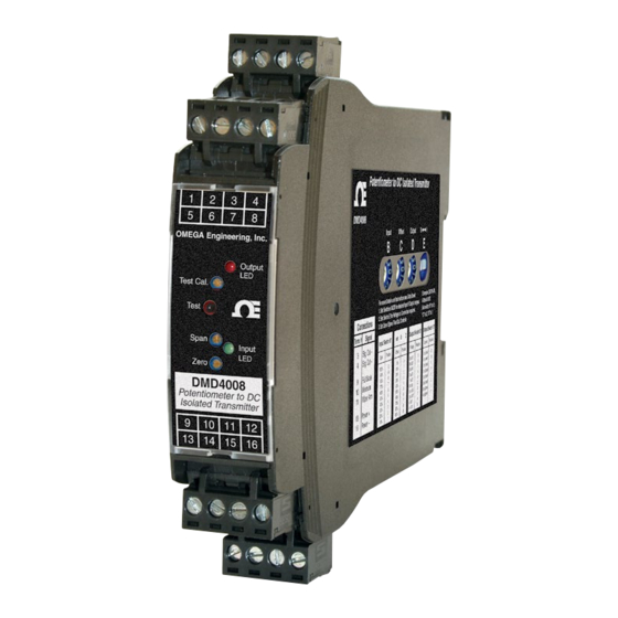
DMD4008
DMD4008-DC
Potentiometer To DC Isolated Signal Conditioners
M-5246/0818
Model
Module Power
DMD4008
85-265 VAC, 50/60 Hz or 60-300 VDC
DMD4008-DC
9-30 VDC or 10-32 VAC
Description
The DMD4008 accepts a resistance input from potentiometer,
slidewire, linear position, displacement, or rotational devices and
provides an optically isolated DC voltage or current output that is
linearly related to the potentiometer position.
The DMD4008 will accept any potentiometer with a value of
0-100 Ω through 0-1 MΩ without recalibration and without
affecting accuracy. A stable 1 VDC source excites the potenti-
ometer. The voltage division ratio is measured using the three
input connections. This measurement method allows the use of
almost any potentiometer without the need for calibration.
The DMD4008 output can be field-configured via external rotary
and slide switches. Offsets and/or input ranges other than 0 to
100% of the potentiometer range can also be selected. Zero and
span potentiometers are provided to fine-tune the output signal.
The full 3-way (input, output, power) isolation makes this module
useful for ground loop elimination, common mode signal rejec-
tion or noise pickup reduction.
Sink/Source Output
Sinking/sourcing versatility allows the DMD4008 to produce
a powered or unpowered mA output allowing it to work with
unpowered or powered mA devices respectively.
The DMD4008 has a 20 VDC loop excitation supply available for
mA outputs. This power supply can be used to power a passive
mA device. If the mA device receiving the output signal already
provides loop power, the DMD4008 output can be wired as a
passive output.
LED Indicators
Two LEDs (green for input, red for output) vary in intensity
with changes in the process input and output signals. These
provide a quick visual picture of your process loop at all times
and can greatly aid in saving time during initial startup and/or
troubleshooting.
Output Test
An output test button provides a fixed output (independent of the
input) when held depressed. The test output level is potentiom-
eter adjustable from 0 to 100% of output span.
The output test button greatly aids in saving time during initial
startup and/or troubleshooting.
Potentiometer Input
Field selectable ranges via switch settings
See table for complete listing
3 wire connection required
0-100 Ω
Minimum:
Maximum:
0-1 MΩ
Input span:
10-100% of potentiometer range
Input offset:
0-90% in 10% increments
Input Impedance
10 MΩ minimum
Common Mode Rejection
120 dB minimum
LoopTracker
Variable brightness LEDs indicate I/O level and status
DC Output Ranges
Field selectable ranges via switch settings
See table for complete listing
Voltage:
0-1 VDC to 0-10 VDC, 10 mA max
Bipolar voltage:
±5 VDC or ±10 VDC
Current:
0-2 mADC to 0-20 mADC
20 V compliance, 1000 Ω at 20 mA
Output Logic
Normal
Output Calibration
Multi-turn zero and span potentiometers
±15% of span adjustment range typical
Output Loop Power Supply
20 VDC nominal, regulated, 25 mADC, <10 mV
May be selectively wired for sinking or sourcing mA output
Output Test
Front button sets output to test level when pressed
Potentiometer adjustable 0-100% of span
Output Ripple and Noise
Less than 10 mV
RMS
Linearity
Better than ±0.1% of span
Ambient Temperature Range and Stability
–10°C to +60°C operating ambient
Better than ±0.02% of span per °C stability
Response Time
70 milliseconds typical
1 millisecond typical with DF option
User's Guide
Shop online at
omega.com
e-mail: info@omega.com
For latest product manuals:
www.omegamanual.info
Lifetime
TM
Isolation
1200 V
minimum
RMS
Full isolation: power to input, power to output, input to output
Housing and Connectors
IP 40, requires installation in panel or enclosure
For use in Pollution Degree 2 Environment
Mount vertically to a 35 mm DIN rail
max. ripple
RMS
Four 4-terminal removable connectors, 14 AWG max wire size
Power
85-265 VAC, 50/60 Hz or 60-300 VDC, 2 W maximum
D versions: 9-30 VDC or 10-32 VAC 50/60 Hz, 2 W maximum
WARNING: This product can expose you to chemicals includ-
ing nickel, which are known to the State of California to cause
cancer or birth defects or other reproductive harm. For more
information go to www.P65Warnings.ca.gov
MADE IN
Advertisement

Related Manuals for Omega DMD4008


Summary of Contents for Omega DMD4008
- Page 1 The DMD4008 has a 20 VDC loop excitation supply available for e-mail: info@omega.com mA outputs. This power supply can be used to power a passive mA device.
- Page 2 For most applications 0-100% of the potentiometer range is 2. Set the input potentiometer to its minimum value to provide used. The DMD4008 can be set up to use part of the potenti- an input to the module equal to the minimum input required ometer range.
- Page 3 DMD4008, DMD4008-DC Potentiometer to DC Isolated Conditioners DMD4008 Range Selection Table The module side label lists common ranges. Use the table below Switch B controls the percent of potentiometer range to use. For ranges that fall between the listed ranges use the next high- for a complete selection of I/O ranges for your application.
- Page 4 Department will issue an Authorized Return (AR) number immediately upon phone or written request. Upon examination by OMEGA, if the unit is found to be defective, it will be repaired or replaced at no charge. OMEGA’s WARRANTY does not apply to defects resulting from any action of the purchaser, including but not limited to mishandling, improper interfacing, operation outside of design limits, improper repair, or unauthorized modification.
Need help?
Do you have a question about the DMD4008 and is the answer not in the manual?
Questions and answers