Table of Contents
Advertisement
Available languages
Available languages
Quick Links
11" (h) x 17" (w)
ENGLISH SIDE
PART# 4-2448, Grev. 2, 06/16
FLUIDMASTER
402CARHR
®
FILL VALVE & FLAPPER
INSTALLATION INSTRUCTIONS
WARNING
DO NOT USE IN-TANK DROP-IN TOILET BOWL CLEANERS CONTAINING BLEACH OR
CHLORINE. Use of such products will: (1) RESULT IN DAMAGE to tank components and MAY
CAUSE FLOODING and PROPERTY DAMAGE and (2) VOID FLUIDMASTER WARRANTY.
Fluidmaster Flush 'n Sparkle Toilet Bowl Cleaning System is recommended for those
choosing to use in-tank bowl cleaners and WILL NOT VOID the FLUIDMASTER WARRANTY
because it will not damage the components. DO NOT overtighten nuts or tank/bowl may crack. Always use quality
Fluidmaster parts when installing or repairing. Fluidmaster will not be responsible or liable for use of non-Fluidmaster parts
during installation or repair.
LIMITED SEVEN-YEAR EXPRESS WARRANTY
Subject to the "Exclusions" set forth below, Fluidmaster Inc. promises to the consumer to repair, or at the option of Fluidmaster Inc. to replace any part
of this plumbing product which proves to be defective in workmanship or materials under normal use for seven years from the date of purchase. All
costs of removal, transportation and reinstallation to obtain warranty service shall be paid by the consumer. During this "Limited Seven Year Express
Warranty," Fluidmaster Inc. will provide, subject to the "Exclusions" section set forth below, all replacement parts free of charge, necessary to correct
such defects. This "Limited Seven Year Warranty" is null and void if this plumbing product has not been installed and maintained in accordance with all
written instructions accompanying the product, and if non-Fluidmaster Inc. parts are used in installation.
EXCLUSIONS: FLUIDMASTER INC. SHALL NOT BE LIABLE FOR INCIDENTAL OR CONSEQUENTIAL DAMAGES, INCLUDING COSTS OF INSTALLATION, WATER
DAMAGE, PERSONAL INJURY OR FOR ANY DAMAGES RESULTING FROM ABUSE OR MISUSE OF THE PRODUCT, FROM OVERTIGHTENING OR FROM FAILURE
TO INSTALL OR MAINTAIN THIS PLUMBING PRODUCT IN ACCORDANCE WITH THE WRITTEN INSTRUCTIONS, INCLUDING USE OF NON-FLUIDMASTER PARTS.
DO NOT USE IN-TANK DROP-IN TOILET BOWL CLEANERS CONTAINING BLEACH OR CHLORINE. USE OF SUCH PRODUCTS WILL RESULT IN DAMAGE TO TANK
COMPONENTS AND MAY CAUSE FLOODING AND PROPERTY DAMAGE. USE OF SUCH PRODUCTS WILL VOID THIS WARRANTY.
Preparing the Fill Valve for Installation
3
Fill Valve Parts
A) Refill Clip
Place Shank
B) Refill Tube
washer onto
"C.L"
MARK
threaded
C) Shank Washer
F
D) Locknut
shank of fill
E) Threaded Shank
valve. Flat
B
G
F) Roller Clamp
side up.
G) Hose Clamps
A
C
E
Shank
Washer
Threaded
D
Shank
Attach Water Supply Connector
6
A. Attach water supply coupling nut to
fill valve – Turn clockwise by hand until tight.
WARNING: Over tightening the nut could damage
fill valve or coupling nut resulting in flooding
A
and property damage. Fluidmaster Click Seal
®
Connector is recommended: a perfect seal every
time without over tightening.
B. To check for leaks, turn on water supply.
C. If leaking occurs – turn coupling nut just
enough to stop leaking.
D. Flush toilet to check.
NOTE: We recommend replacing the existing
water supply connector if it is worn or over 5
B
years old – this will protect your home from
potential flooding and property damage.
IF FILL VALVE DOES NOT TURN ON, WILL NOT
TURN OFF, OR WILL NOT REFILL THE TANK
AFTER THE FLUSH
• Remove top cap and check for debris. If you find debris, or flow
is weak: Inspect lower section of fill valve for partial blockage.
Partial blockage may be at shut off valve or in water supply line
(See "REMOVING THE VALVE CAP ASSEMBLY & FLUSHING OUT
DEBRIS").
• If fill valve has been in use for some time and/or float cup does not
drop when flushing tank, replace seal with a genuine Fluidmaster 242
seal (See "IF REPLACING SEAL").
– Please keep a copy of these instructions on the property in which the product was installed.
TANK
ROLLER CLAMP
LEVER
REFILL TUBE
FLOAT
CUP
LOCK RING
FILL
FLAPPER
VALVE
SHANK
WASHER
LOCKNUT
Fill Valve Positioning:
MEASURE
HEIGHT ONLY:
A. Position fill valve in tank – DO NOT FULLY
DO NOT INSTALL
INSTALL.
1
"
B. Set top of fill valve 3" above overflow pipe.
Fill Valve Height Adjustment – If Necessary:
LOCK
A. DO NOT MOVE LOCK RING.
RING
B. Increase height – twist lower shank counter
clockwise.
C. Decrease height – twist lower shank clockwise.
D. Critical Level Mark (C.L Mark) MUST be
positioned 1" above top of overflow pipe –
required by Universal Plumbing Code.
DO NOT
MOVE
LOCK RING!
Adjusting Tank Water Level
7
HINT: When adjusting float cup, flush tank and
make adjustment while tank is filling.
A. Turn water on.
B. Turn water level adjustment screw to set
float cup to desired level.
C. Turning adjustment screw clockwise raises
water level.
D. Turning adjustment screw counter
clockwise lowers water level.
E. Flush toilet to check new level.
HINT: Twisting adjustment screw 8 times
moves float by 1/2".
IF FILL VALVE TURNS ON AND OFF BY ITSELF
• This indicates the tank is losing water. The fill valve is refilling lost water.
Clean flapper and drain seat. If leak continues change flush valve. Install
Fluidmaster 507AKR, 540AKR or 555C kit.
IF WATER LEVEL IN BOWL IS TOO LOW
• Make sure the refill tube is supplying water down overflow pipe.
• Water level in tank may be too low. Raise water level to 1/2" below top
of overflow pipe (See Step "7"). You may have to lengthen the fill valve
in order to increase the water level in tank (See Step "3").
• Flapper may be closing too soon. Give flapper chain approximately 1/2"
of slack (See Step "5").
TOOLS
NEEDED
Scissors
Sponge
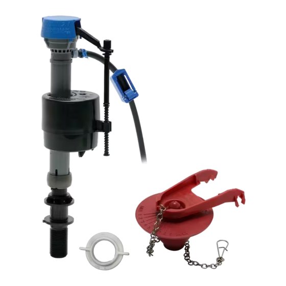
PARTS
1
HOSE CLAMP
IN THIS KIT:
REFILL CLIP
(1) PerforMAX™ Fill Valve
(1) Shank Washer
(1) Locknut
OVERFLOW
PIPE
(1) Refill Tube
(1) Refill Clip
FLUSH
(1) Roller Clamp
VALVE
(2) Hose Clamps
TANK SHOULD
Before you begin, watch
LOOK LIKE THIS
(1) PerforMAX™ High
WHEN SET UP IS
our installation video:
COMPLETE
Performance Flapper
http://opn.to/a/PV6p9
Installing New Fill Valve
4
A. Place fill valve in tank.
B. Align fill valve nipple to face overflow pipe.
C. Press down on shank from inside while tightening
locknut.
D. Hand-tighten only – DO NOT OVERTIGHTEN!
Overtightening may crack fill valve or tank causing
flooding.
E. Attach one end of refill tube (b) to refill clip (a).
F. Place clip on right side of overflow pipe.
G. Attach other end of tube to nipple on fill valve – Cut
tube as necessary.
H. Squeeze tube clamps and slide to ends of tube and
release.
WARNING: Placing refill tube down overflow pipe may
cause significant water waste.
Water-Saving Feature: Roller Clamp
8
HINT: Flush toilet – if bowl appears full, but continues to fill, valve
may be overfilling bowl. Adjust water level as follows:
A. Fill bowl with gallon of water & wait for it to recede and stop.
B. Mark water level with pencil and flush toilet. If the water refills
above line, water level is too high, if water stops filling below pencil
line, water is too low.
C.Adjust water by pushing down and rolling the dial with thumb on
roller clamp. "0" means no refill.
Removing Valve Cap, Flushing Out Debris, Replacing Seal & Replacing Valve Cap
Removing Valve Cap
Turn off water supply.
Flush Toilet. Twist
counter-clockwise
to remove cap and
disconnect from rod.
242
SEAL
DON'T
30800 Rancho Viejo Road, San Juan Capistrano, CA 92675
USE
www.Fluidmaster.com • 800-631-2011
Contact Fluidmaster for troubleshooting help or visit www.fluidmaster.com
M-F 5:30 am - 5:00 pm PST.
Remove Old Fill Valve & Flapper
2
C
Remove tank lid. Use pencil to mark water level of
tank. Then follow steps A-E.
A. Turn off water supply (Clockwise). Flush toilet and remove
excess water from tank with sponge.
B. Disconnect water supply connector. Remove locknut from
under tank.
C. Remove fill valve from tank.
B
D. Unhook flapper chain from tank lever.
E. Remove flapper from overflow pipe on flush valve.
D
A
Installing New PerforMAX™ High
5
Performance Flapper
A. Put flapper on seat.
Correct set up of refill
B. Align flapper clips with horizontal
tube and refill clip to
posts of overflow pipe.
overflow pipe
C. Push down on clips to connect.
D. Attach chain clip to tank lever – Leave
b
about 1/2" of slack in chain.
a
E. Turn rubber portion of flapper left or
NIPPLE
right to adjust performance level.
F. Clockwise for greater flush volume.
G. Counterclockwise for lower flush
volume.
Code Compliance
9
Once fill valve is installed, ensure overflow
pipe and water level of tank are correctly set.
1. THE TOP OF OVERFLOW PIPE (A) must be
minimum of 1" below TANK LEVER HOLE (B).
2. WATER LEVEL (C) is set below top of Overflow
Pipe (Fluidmaster recommends 1/2").
3. THE CRITICAL LEVEL MARK / C.L. Mark (D)
identified by C.L. on fill valve must be positioned 1"
above top of overflow pipe. This is a requirement of
the Universal Plumbing Code.
Code Compliance helps protect your home &
Hose
drinking water supply.
Clamps
Flushing Out Debris
If Replacing
Hold cup upside down over
Seal
uncapped valve to prevent
splashing. Turn water supply
on and off a few times. Turn
water supply off when putting
cap back on valve.
SEAL
LOCATION
If Replacing Seal:
Use only a genuine
Fluidmaster 242 seal.
E
HORIZONTAL
FLAPPER CLIPS
POSTS
SEAT
D
B
WATER
LEVEL
A
C
OVERFLOW
FILL
PIPE
VALVE
Replacing Valve Cap
Connect cap to rod (a). If you have
a 400 with a metal rod (c), place
adapter (b) into slot at end of cap.
Place cap on valve with rod next to
refill tube (d). Push down and twist
clockwise until it stops.
a
d
b
c
Advertisement
Table of Contents

Related Manuals for Fluidmaster 402CARHR


Summary of Contents for Fluidmaster 402CARHR
- Page 1 E. Remove flapper from overflow pipe on flush valve. LIMITED SEVEN-YEAR EXPRESS WARRANTY (2) Hose Clamps Subject to the “Exclusions” set forth below, Fluidmaster Inc. promises to the consumer to repair, or at the option of Fluidmaster Inc. to replace any part TANK SHOULD Before you begin, watch of this plumbing product which proves to be defective in workmanship or materials under normal use for seven years from the date of purchase.
- Page 2 ARANDELA mire nuestro video de o reinstalación de la unidad para obtener el servicio de la garantía deberán ser abonados por el consumidor. Durante esta "Garantía expresa limitada por siete años", Fluidmaster Inc. DEBE VERSE ASÍ (2) Abrazaderas para manguera proporcionará...
Need help?
Do you have a question about the 402CARHR and is the answer not in the manual?
Questions and answers