
Related Manuals for Snap-On Sun SWB 100


Summary of Contents for Snap-On Sun SWB 100
- Page 1 WHEEL BALANCER •OPERATOR’S MANUAL EQUILIBREUSE DE ROUES •NOTICE D’ UTILISATION RADAUSWUCHTMASCHINE •BETRIEBSANLEITUNG SWB 100...
- Page 2 }ON - je u skladu sa svim relevantnim odredbama slede2ih direktiva: NLD - overeenstemt met alle toepasselijke voorschriften van de volgende richtlijnen: Snap-on Equipment Srl - Via Provinciale per Carpi, 33 - 42015 Correggio (RE) Italy POL - jest zgodna ƒjest zgodny„ ze wszystkimi zarz…dzeniami zawartymi w nast†puj…cych dyrektywach: RU} - este fabricat în conformitate cu toate prevederile în materie din urmãtoarele directive:...
- Page 3 - NOTES REGARDING DOCUMENTATION - ITA NOTE SULLA DOCUMENTAZIONE - ANMERKUNGEN ZUR DOKUMENTATION - SPA NOTAS SOBRE LA DOCUMENTACIÓN - NOTES SUR LA DOCUMENTATION - POR - ПРИМЕЧАНИЯ ПО ДОКУМЕНТАЦИИ NOTAS SOBRE A DOCUMENTAÇÃO Product aid publication: Pubblicazione di supporto al prodotto: WHEEL BALANCER EQUILIBRATRICE Zum Produkt gehörendes Dokument:...
-
Page 4: Table Of Contents
DISCLAIMER OF WARRANTIES UPDATING REPORTS AND LIMITATIONS OF LIABILITIES While the authors have taken care in the preparation Revision A of June 2016 of this manual, nothing contained herein: First document issue PCN: 16G0160 modifi es or alters in any way the standard terms and conditions of the purchase, lease or rental agreement under the terms of which the equipment to which this manual relates was... - Page 5 LIMITES D’APPLICATION DE LA GARANTIE ET GEWÄHRLEISTUNGS- UND LIMITATIONS DE LA GARANTIE HAFTUNGSAUSSCHLUSS Bien que les auteurs aient accordé la plus grande Die Informationen in dieser Bedienungsanleitung wurden attention à la rédaction du présent manuel, aucun gewissenhaft und sorgfältig zusammengestellt. Der Inhalt élément fi...
-
Page 6: Safety
Safety Safety Important safety precautions relevant to the unit are described in the Safety Booklet, refer to Figure 1 – 1. The Safety Precautions should be fully understood and observed by every operator. We suggest you store (a copy) of the Safety Booklet near the unit, within easy reach of the operator. - Page 7 Sécurité Sicherheit Sécurité Sicherheit Les mesures de sécurité importantes relatives à l’unité Wichtige Sicherheitsmaßnahmen für dieses Gerät sont décrites dans le Livret de Sécurité et résumées sind im Sicherheitshandbuch beschrieben; siehe Figure 1-1. Abbildung 1-1. Chaque opérateur doit totalement comprendre les Die Sicherheitsmaßnahmen müssen von allen mesures de sécurité.
-
Page 8: Specifi Cations
Specifi cations 2.0 Specifi cations Power: Power Supply 230V~, 50/60 Hz, 1 ph 1,1 A Power consumption 0,12 KW Motor rating Mains fuses (2x)IEC 127 T 6,3A Measurements: Measuring time >6 sec. Measuring speed <100 rpm 0–250 mm Offset 1/5 g o 0,05/0,25 oz Resolution Wheel dimensions: 20”... - Page 9 Specifi cations Spezifi kationen 2.0 Specifi cations 2.0 Spezifi kationen Données électrices : Strom: Alimentation 230V~, 50/60 Hz, 1 ph Stromversorgung 230V~, 50/60 Hz, 1 ph Consommation électrique 1,1 A 1,1 A Stromverbrauch Puissance moteur 0,12 KW 0,12 KW Motorwerte Fusibles (2x)IEC 127 T 6,3A Netzsicherungen...
-
Page 10: Introduction
Introduction 3.0 Introduction This wheel balancer combines advanced, high- performance technology, robustness and reliability with very simple, user-friendly operation. The low rotation speed of the wheel ensures that this balancer is very safe. It is characterised by a display and input panel which are easy to use and guarantee rapid, intuitive operation. - Page 11 Introduction Einführung 3.0 Introduction 3.0 Einführung Cette équilibreuse vous offre une technologie avancée Dieses Auswuchtgerät verbindet hochmoderne de haute performance, solidité et fiabilité et son Hochleistungstechnik, Robustheit und Zuverlässigkeit opération est très simple et conviviale. mit einfachem, benutzerfreundlichem Betrieb. La faible vitesse de rotation de la roue assure que Durch die niedrige Rotationsgeschwindigkeit des cette équilibreuse peut être utilisée en toute sécurité.
- Page 12 Accessories Accessories Refer to Figure 3.1-1. The standard accessories are: Quick-Release Hub Nut EAA0263G66A Quick-clamping MZV (Ring-Nut) EAA0277G61A Spacer ring EAC0058D08A Universal drum EAC0058D07A Universal drum cushion EAC0058D15A Large cone EAM0005D25A Medium cone EAM0005D24A Small cone EAM0005D23A User Calibration weight EAM0005D40A Weight pliers 8-04250A...
- Page 13 Accessoires Zubehör Accessoires Zubehör Se reporter à la Figure 3.1-1. Siehe Abbildung 3.1-1. Les accessoires standard sont: Das folgende Standardzubehör steht zur Verfügung: Manivelle de serrage rapide Schnellspannmutter EAA0263G66A EAA0263G66A Ecrou à serrage rapide MZV Quickmutter MZV EAA0277G61A EAA0277G61A Disque de distance Distanzring EAC0058D08A EAC0058D08A...
-
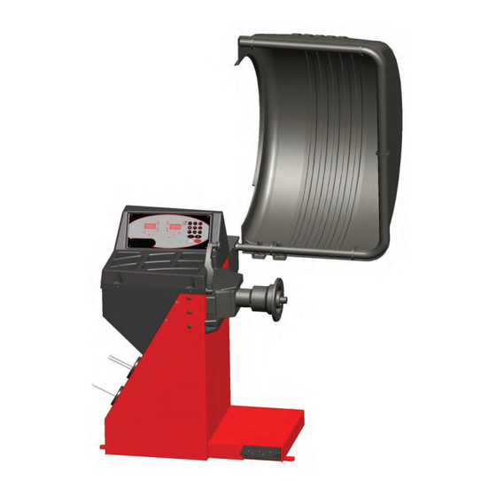
Page 14: Layout
Layout 4.0 Layout Refer to Figure 4-1. Functional description of the unit: 1. Display Refer to Chapter 4.1. 2. Input panel Refer to Chapter 4.2. 3. Internal gauge arm 4. Flange 5. Stub shaft 6. Weight compartments 7. Storage areas for cones and hub nuts 8. - Page 15 Disposition Layout 4.0 Disposition 4.0 Layout Se reporter à la Figure 4-1. Siehe Abbildung 4-1. Description fonctionnelle de la machine : Funktionsbeschreibung des Geräts: 1. Affi chage 1. Display Se reporter au Chapitre 4.1 Siehe Kapitel 4.1. 2. Clavier 2. Eingabefeld Se reporter au Chapitre 4.2 Siehe Kapitel 4.2.
- Page 16 Layout The display Refer to Figures 4.1-1. 1. Rotation indicators of the correction plane. The indicators show the direction the operator has to rotate the wheel (by hand) after a balancing run. 2. Weight Application Position (WAP) indicator. The indicator will light up when the wheel is in the correct position for weight application.
- Page 17 Disposition Layout L’affi chage Das Display Se reporter à la Figure 4.1-1. Siehe Abbildungen 4.1-1. 1. Indicateurs de position de masses correctives 1. Rotationsanzeige der Korrekturebene. Les indicateurs indiquent la direction vers laquelle Die Anzeigen geben die Richtung an, in der l’opérateur doit tourner la roue (manuellement) der Bediener das Rad (per Hand) nach einer après un équilibrage.
- Page 18 Layout The input panel Refer to Figure 4.2-1. 1. Diameter key with indicator. Press to select “rim diameter” mode, the current diameter or “dia” value will appear and the unit will beep. The current value will be shown on the display and can be edited.
- Page 19 Disposition Layout Le Panneau de Données Das Eingabefeld Se reporter à la Figure 4.2-1. Siehe Abbildung 4.2-1. 1. Touche diamètre avec indicateur 1. Durchmesser-Taste mit Anzeige. Appuyer sur cette touche pour sélectionner le mode D r ü c k e n S i e d i e s e Ta s t e , u m d e n “diamètre de jante”.
- Page 20 Layout Weight Press to select the required weight application mode (weight mode), the unit will beep. F+Weight key; activates the Motorcycles wheel balancing Mode. 9. Stop key. Press to stop spinning the wheel. The STOP key also has an emergency stop function.
- Page 21 Disposition Layout 8. Touche de Masse 8. Gewicht-Taste. Appuyez pour sélectionner le mode de pose des Drücken Sie diese Taste, um den gewünschten masses requis (mode de poids), l’unité émet un Gewichtsanbringungsmodus (Gewichtsmodus) bip sonore. zu wählen. Das Gerät piept. F+Touche de Masse ;...
-
Page 22: Operation
Operation 5.0 Operation This chapter describes how to operate the unit in order to balance a wheel. The standard balancing runs will be described fi rst. In chapter 5.4 and up special modes and functions will be described. Be sure to be familiar with: possible dangers, refer to chapter 1 the unit, refer to chapter 4. - Page 23 Utilisation Betrieb 5.0 Utilisation 5.0 Betrieb Ce chapitre décrit l’utilisation de la machine pour In diesem Kapitel wird beschrieben, wie mit dem Gerät équilibrer une roue. ein Rad ausgewuchtet wird. Les étapes d’équilibrage standard sont décrites en Zuerst werden die standardmäßigen Auswuchtvorgänge premier.
- Page 24 Operation 5.2 Preparation • The operator should be familiar with the warnings and cautions. • The operator should be qualifi ed to work with the unit. • Always ensure that the wheel guard (when applicable) is lifted and the gauge arm is in its home position (far left position) when the unit has been switched off.
- Page 25 Utilisation Betrieb Préparation Vorbereitung • Der Bediener muss mit den Warnhinweisen und • L’opérateur doit se familiariser avec les Vorsichtsmaßnahmen vertraut sein. avertissements et les mesures de sécurité. • L’opérateur doit être formé pour travailler avec la • Der Bediener muss für die Arbeit mit dem Gerät machine.
- Page 26 Operation 5.2.3 Shutting down Always shut down properly when work is complete: • Remove the wheel from the balancer. • Remove the cones and hub nut from the stub shaft. Check the surfaces (internal and external) of the cones for damage. The condition of the cone is very important for a good balance quality.
- Page 27 Utilisation Betrieb 5.2.3 Arrêt 5.2.3 Abschalten À la fi n du travail compléter toujours les opérations de Schalten Sie das Gerät am Ende einer Arbeitsschicht façon convenable: immer ordnungsgemäß ab: • Retirer la roue de l’équilibreuse. • Nehmen Sie das Rad von dem Auswuchtgerät. •...
- Page 28 Operation Balancing procedure The unit always has a weight mode automatically selected, refer to the display. Select the appropriate key (1 - Fig.5.3-1) to scroll through the weight modes continuously. The weight mode currently selected is shown by the illuminated indicator(s). NORMAL Used for steel rims.
- Page 29 Utilisation Betrieb Procédure d’équilibrage Auswuchtvorgang La machine a toujours un type de mode d’équilibrage D a s G e r ä t z e i g t i m m e r a u t o m a t i s c h e i n e n sélectionné...
- Page 30 Operation 5.3.1 Rim data input Dimensions can be measured by hand and then typed in on the keyboard. Dimension Units diameter: inches (default) or mm. rim width: inches (default) or mm. offset: millimetres. To change the units, refer to Chapter 5.2.4.2. 5.3.1-1 MANUAL data entry Manual data entry is required only if the gauge arm...
- Page 31 Utilisation Betrieb 5.3.1 Entrée Paramètres Roue 5.3.1 Eingabe der Felgendaten Les dimensions peuvent être mesuré manuellement Die Maße können manuell gemessen werden und über et vous insérez par clavier. die Tastatur eingegeben werden. Dimension Unités Maße Einheiten diamètre: Pouce (défaut) ou mm. Durchmesser: Zoll (Standard) oder mm.
- Page 32 Operation 5.3.2 Balancing This chapter describes how to balance a wheel. For help on: rim data input refer to Chapter 5.3.1 spinning the wheel refer to Chapter 5.3.3 weight application refer to Chapter 5.3.4 the check spin refer to Chapter 5.3.5 5.3.2.1-1 5.3.2.1 Normal weight mode...
- Page 33 Utilisation Betrieb 5.3.2 Equilibrer un type de roue 5.3.2 Auswuchten Ce chapitre décrit comment équilibrer une roue. In diesem Kapitel wird das Auswuchten eines Rades Pour des renseignements sur: beschrieben. Hier fi nden Sie Hilfe zu den folgenden Themen: Entrée données jante voir Chapitre 5.3.1 Eingabe von Felgendaten Kapitel 5.3.1...
- Page 34 Operation 5.3.2.3 Alu2 and Alu3 (HWM) mode Select this mode for more exact balancing, weight positioning behind spokes or special rims (PAX, TRX, CTS, etc.). When selected, the display shows: HWM1: Refer to Figure 5.3.2.3-1. Two stick-on weights. HWM2: Refer to Figure 5.3.2.3-2. 5.3.2.3-1 Left plane: clip-on weight Right plane: stick-on weight.
- Page 35 Utilisation Betrieb 5.3.2.3 Mode des masses Caché 5.3.2.3 Modus “ALU 2” und “ALU 3” (HWM) Sélectionner cette fonction pour un équilibrage plus Wählen Sie diesen Modus, um eine exaktere correct ; pour la pose des masses derrière les rayons, Auswuchtung zu erzielen, um das Gewicht hinter ou pour les jantes spéciales (PAX, TRX, CTS, ecc.).
- Page 36 Operation 5.3.3 Spinning the Wheel The wheel data must be acquired and the type of rim to be used must be entered. With Code C13 set on “1”; • Close the wheel guard. With Code C13 set on “0”; • Close the wheel guard and press START. The motor starts up and the wheel spins.
- Page 37 Utilisation Betrieb 5.3.3 Lancement roue 5.3.3 Der Messlauf Les paramètres de la roue et du type de jante utilisée Die Raddaten müssen erfasst sein, danach geht man doivent avoir été préalablement saisis. folgendermaßen vor: Avec le Code C13 paramétré “1”; Wenn der Code C13 auf „1”...
- Page 38 Operation The weight to be applied in that plane is shown on the display. • Turn the wheel manually until it reaches the counterweight application point Attaching a clip-on weight. Refer to Figure 5.3.4-5. • Clip-on weights must always be applied in the 12 o’clock position.
- Page 39 Utilisation Betrieb La valeur de la masse à appliquer sur ce plan est Das Gewicht, das in der Ebene angebracht werden montrée sur l’affi cheur. muss, wird auf dem Display angegeben. • Tourner la roue manuellement tant que la position Drehen Sie das Rad mit der Hand, um es in die •...
- Page 40 Operation 5.3.5 Check spin It is good practice to perform a check spin after applying the weights. • Spin the wheel. If the wheel has been balanced properly, “000” will be displayed for both planes. To check how much imbalance is left: •...
- Page 41 Utilisation Betrieb 5.3.5 Tour de roue de contrôle 5.3.5 Kontrolllauf Il est conseillé d’effectuer un lancement de contrôle Es ist ratsam, nach Anbringen der Gewichte zur après avoir appliqué les masses. Bestätigung einen Kontrolllauf durchzuführen. • Effectuer le lancement de la roue. •...
- Page 42 Operation Special modes Selecting the F key enables the operator to scroll the following modes in sequence: Split Weight Mode (SWM), Minimisation mode. 5.4.1 Split Weight Mode Selecting is possible only after balancing a HWM wheel that has an imbalance ≥...
- Page 43 Utilisation Betrieb Modes spéciaux Besondere Modi La sélection de la touche F (1, fi gure 5.4.1-2) permet Durch Drücken der “F” (1, Abb. 5.4.1-2) Taste kann à l’opérateur de dérouler en séquence: der Bediener nacheinander Folgendes durchlaufen: Mode Masses Divisées (SWM), Modus Getrenntes Gewicht (SWM), Mode Minimisation.
- Page 44 Operation If optimisation is not required, weight minimisation (also known as matching) is possible. For example, when the rim has no shape defects, meaning that wheel imbalance depends exclusively on tyre irregularities. In such cases, the rim imbalance may be positioned relative to the tyre imbalance so that they compensate one another and the machine calculates a minimum correction weight.
- Page 45 Utilisation Betrieb Si une optimisation n’est pas souhaitée, il est pos- in der Regel, sofern vorhanden, Höhen– und Seitenschlag sible d’obtenir une minimisation des masses (appelée sowie Radial– und Seitenkraftschwankungen verringert und “matching”). somit die Laufruhe des Rades optimiert. Außerdem kann die zum Auswuchten notwendige Masse (Ausgleichsgewicht) Ceci est par exemple possible si la jante ne présente reduziert werden.
- Page 46 Operation • Press the PRO-MATCH key (2). The OP.1 reading appears. In all fi gures in which the valve symbol appears on the edge of the rim, shift the tyre on the rim then press the PRO-MATCH key (2) to set the valve position (exactly perpendicular to and above the main shaft).
- Page 47 Utilisation Betrieb Une correction ultérieure n’est plus possible. • Soll die Laufruhenoptimierung durchgeführt • Démonter le pneu et serrer la jante pour effectuer werden, prüfen Sie, ob die Felgenmaße korrekt une lancée de compensation. eingegeben sind. • Appuyer sur la touche PRO-MATCH (2). Nachträgliche Korrekturen sind nicht möglich.
- Page 48 Operation • Position the valve exactly perpendicular to and above the main shaft. • Press the PRO-MATCH key (2) to acquire the valve position. OP.4 appears. • Press the START key. The measuring run is carried out. After the measuring run two readings are possible: OP.5 - H1 Further optimisation is not recommended, but possible.
- Page 49 Utilisation Betrieb • Appuyer sur la touche PRO-MATCH (2) pour entrer • Die Taste PRO-MATCH (2) drücken, um die la position de la valve. Ventilposition zu übernehmen. L’affi chage OP.4 apparaît alors. Es erscheint die Anzeige OP.4. • Appuyer sur la touche START (3). •...
- Page 50 Operation Silent running cannot be improved. However, it is possible to readjust the tyre relative to the rim to achieve signifi cant weight minimisation (i.e.: smaller balance weights) without having an adverse effect on silent running. Depending on the readings, there are several possibilities for proceeding with the program.
- Page 51 Utilisation Betrieb atteindre une minimisation considérable des masses ist jedoch eine beträchtliche Gewichteminimierung d’équilibrage (donc de plus petites masses), sans avoir (kleinere Ausgleichsgewichte) möglich, ohne die un effet négatif sur la stabilité de marche. Laufruhe zu verschlechtern. En fonction des affichages, il existe plusieurs Je nach Anzeige sind verschiedene Möglichkeiten possibilités de poursuivre le programme.
- Page 52 Operation indicator and make a double mark on the right side of the tyre exactly perpendicular to and above the main shaft. • Remove the wheel from the machine • Readjust the tyre on the rim until the double mark coincides with the valve.
- Page 53 Utilisation Betrieb Recommandation de tourner la pneu sur la jante (les Es wird die im Rad vorhandene Unwucht angezeigt. traits de l’affi chage droit restent allumés). • Den Ausgleich gemäß Anzeige vornehmen. Sélection 1 : Tourner le pneu sur la jante (programme standard).
- Page 54 Operation Weight minimisation program cycle If the rim compensation run was omitted and the F key (1) was pressed to go directly into the minimisation program (reading Un.), proceed as follows. • Clamp the wheel. • Position the valve exactly perpendicular to and above the main shaft.
- Page 55 Utilisation Betrieb Sélection 2: Interruption d’optimisation • Durch Drücken der F–Taste im Programm weiterschalten. • Repasser au programme d’équilibrage en appuyant Es erscheint die Anzeige === - Un.7 oder Un.7 - === sur la touche STOP (4) et effectuer l’équilibrage Wahlmöglichkeit 2: Laufruhenoptimierung abbrechen suivant les affi...
- Page 56 Operation the tyre be readjusted on the rim. The optimum minimisation condition has been achieved and cannot be improved. Depending on the readings, there are several possibilities for proceeding with the program. These possibilities are described below. Reading === - Un.7 Turn the tyre over on the rim (the left display bars are rotating).
- Page 57 Utilisation Betrieb Il est recommandé de renverser le pneu sur la jante. === - Un.7 Mit dem UN–Programm fortfahren. Wenden des Un.7 - === Reifens empfohlen. Poursuivre le programme . Il est recommandé de tourner le pneu sur la jante. Un.7 - === Mit dem UN–Programm fortfahren.
- Page 58 Operation (normal program) - Readjust the wheel according to the right direction indicator and make a double mark on the right side of the tyre exactly perpendicular to and above the main shaft. - Remove the wheel from the machine. - Readjust the tyre on the rim until the double mark coincides with the valve.
- Page 59 Utilisation Betrieb affi chages. Bei Anzeige Un.7 - === Empfehlung zum Drehen des Reifens auf der Felge (die Striche der rechten Anzeige leuchten ständig). Affi chage Un.7 - === Recommandation de tourner la roue sur la jante (les Wahlmöglichkeit 1: Reifen auf der Felge drehen traits de l’affi...
- Page 60 Operation Special functions In this chapter all functions that may be accessed by the operator are described. A special function is a “mode” that is not necessarily required to balance a wheel properly. 5.5.1 Non-skid function On wheels with a limited weight, skid specifi cations may make it impossible to perform a run at the normal measuring speed.
- Page 61 Utilisation Betrieb Besondere Funktionen Fonctions spéciales Dans ce chapitre sont décrites toutes les fonctions In diesem Kapitel werden alle Funktionen beschrieben, auxquelles l’opérateur a accès. Une fonction est un zu denen der Bediener Zugang hat. Eine Funktion ist “mode” qui n’est pas nécessaire pour un équilibrage ein „Modus”, der nicht unbedingt benötigt wird, um ein correct d’une roue.
- Page 62 Operation Calibration This chapter describes the calibrations that can be performed by the operator. 5.6.1 User calibration If a number of different measuring runs have to be performed to balance a wheel and the values and positions of the weights have to be changed, it generally means that measuring is not precise.
- Page 63 Utilisation Betrieb Procédure de calibration 5.6 Tarierung Ce chapitre contient les procédures de calibration In diesem Kapitel werden die Tarierungen beschrieben, accessibles à l’utilisateur. die vom Bediener durchgeführt werden können. 5.6.1 Etalonnage par l’opérateur 5.6.1 Nachjustage Wenn zum Auswuchten eines Rads mehrere Messläufe Si plusieurs lancées de mesure sont nécessaires mit Korrekturen am Wert und an der Stellung der pour équilibrer une roue parce que la grandeur et...
- Page 64 Operation “MODE” Selecting the operating mode To use the balancer normally you do not need to change the operating mode and the relative states set by the manufacturer. In special cases, however, or if working conditions require it, the operating modes and states can be changed by entering the appropriate codes.
- Page 65 Utilisation “MODE” Betrieb “MODUS” 5.7 Auswahl des Betriebsmodus S é l e c t i o n d u m o d e d e fonctionnement Für den normalen Betrieb der Auswuchtmaschine ist es nicht nötig, die Betriebsmodi und die entsprechenden, vom Hersteller programmierten Zustände zu verändern.
- Page 66 Operation “MODE” Code C0 Figure 5.7-3 setting operating modes preset by the manufacturer No action Set values preset by the manufacturer (state 1 is displayed only briefl y) The operating mode selected can be obtained from the permanent memory. 5.7-3 Code C1 Figure 5.7-4 Selecting the defi...
- Page 67 Utilisation “MODE” Betrieb “MODUS” Code C0 Code C0 Fig. 5.7-3 Etablir les modes de fonctionnement pro- Abbildung 5.7-3 Einstellung der vom Hersteller grammés par le fabricant festgelegten Betriebsmodi. = Aucune action 0* = Keine Aktion 1 = Einstellung der vom Hersteller vorgegebenen = Etablir les valeurs programmées par le fabricant (l’état 1 n’est affi...
- Page 68 Operation “MODE” Code C4 Figure 5.7-7 Eventual residual clamping device imbal- ance compensation. High precision measuring (This operating mode cannot be stored in the permanent memory). Once compensation has been performed, if the clamp- ing device is changed, this value must be deleted or recalculated using the new device.
- Page 69 Utilisation “MODE” Betrieb “MODUS” Code C4 Code C4 Fig. 5.7-7 Compensation électrique d’un éventuel Abbildung 5.7-7 Ausgleich der eventuell in der balourd résiduel dans le moyen de serrage. Spannvorrichtung vorhandenen Restunwucht. Mesure à précision élevée (ce mode ne peut pas être Messung mit hoher Präzision (dieser Betriebsmodus enregistré...
- Page 70 Operation “MODE” Code C8 Figure 5.7-10 Selecting the threshold value for sup- pressing minor imbalances in grams or oz. The unit of measure depends on the C3 code setting. Grammes: Range 5 to 20.0 g Factory-adjusted to 5 g Read out limit, e. g. 5 g Select another limit, e.
- Page 71 Utilisation “MODE” Betrieb “MODUS” Code C8 Code C8 Fig. 5.7-10 Choix de la limite pour la suppression de Abbildung 5.7-10 Auswahl des Schwellenwerts zur faibles balourds, en grammes ou onces. L’unité de Unterdrückung kleiner Unwuchten in Gramm oder in mesure (g ou oz) dépend des entrées faites avec C3. Unzen.
- Page 72 Operation “MODE” Code C14 User recalibration (refer to the relevant Figure 5.7-13 section). Code C21 Figure 5.7-14 This displays the program version number and the model number. E.g.: Program version 3.4.18 for Mid. model. 5.7-13 • to display the program version number release the C key.
- Page 73 Utilisation “MODE” Betrieb “MODUS” Code C14 Code C14 Etalonnage de la machine par l’opérateur Vom Benutzer durchgeführte Fig. 5.7-13 Abbildung 5.7-13 (voir la rubrique correspondante). Neutarierung der Maschine (siehe dazu das entsprechende Kapitel). Code C21 Code C21 Fig. 5.7-14 Lecture du numéro de la version du Abbildung 5.7-14 Anzeige der Nummer der programme et de la machine.
-
Page 74: Maintenance
Maintenance 6.0 Maintenance This unit is designed to operate for a long time. At start-up the operator should check if all indicators and displays light up. If the operator shuts down correctly (Chapter 5.2.3) at the end of each shift, no further maintenance is required. - Page 75 Entretien Wartung 6.0 Wartung 6.0 Entretien Cette machine est conçue pour vous donner un Dieses Gerät wurde entwickelt, um viele Stunden nacheinander arbeiten zu können. service de longue durée. Dans le mode de démarrage, l’opérateur doit vérifi er que tous les indicateurs et affi...
- Page 76 Trouble shooting 7.0 Trouble shooting If a problem arises with the wheel balancer, proceed in the following order to solve the problem: 1. Rethink the last steps taken. Did you work according to the manual? Did the unit work as described and expected? 2.
- Page 77 Dépannage Fehlerbeseitigung 7.0 Dépannage 7.0 Fehlerbeseitigung En cas de problème avec l’équilibreuse, procéder Sollte ein Problem mit dem Auswuchtgerät auftreten, comme suit pour résoudre le problème : gehen Sie bitte in der nachfolgend beschriebenen Reihenfolge vor, um das Problem zu lösen: 1.
- Page 78 Trouble shooting Gauge arm inputs differ from wheel dimensions stated on rim or tyre. 1. Did you position the gauge arm correctly? • Refer to Chapter 5.3.1. 2. Check the offset input of the gauge arm by entering manually. • Refer to the scale on the gauge. •...
- Page 79 Dépannage Fehlerbeseitigung Paramètres de la jauge diffère des dimensions de Die Eingabewerte des Messarms stimmen nicht jante indiquées sur la jante ou le pneu. mit den Angaben auf der Felge oder dem Reifen 1. Avez-vous positionné correctement la jauge de überein.
- Page 80 Trouble shooting System messages The wheel balancer can show messages to the operator. These may be error related (E-codes) or warnings (H-codes). The codes will be described in the following chapters. Whenever a code appears: • make a note of it; •...
- Page 81 Dépannage Fehlerbeseitigung Messages de système Systemmeldungen L’équilibreuse peut afficher des messages pour Das Auswuchtgerät kann dem Bediener Meldungen l’opérateur. Ces messages peuvent indiquer des machen. Diese können sich auf Fehler (E-Codes) erreurs (Codes E) ou des problèmes de service (Codes beziehen oder Warnungen (H-Codes) sein.
- Page 82 Trouble shooting Optimisation / minimisation was not carried out correctly. 1. Wheel was not exactly centred on clamping means for at least one run. 2. Tyre was not centred on rim for at least one run. 3. Valve position was not set and acquired correctly at least once.
- Page 83 Dépannage Fehlerbeseitigung Exécution incorrecte de la lancée d’Optimisation/ Die Optimierung / Minimierung wurde fehlerhaft Minimisation. durchgeführt. 1. La roue n’était pas centrée exactement sur le 1. Das Rad war bei mindestens einem Lauf nicht exakt moyen de serrage au moins une fois pendant les auf dem Spannmittel zentriert.
- Page 84 Trouble shooting A key is jammed. Find and release jammed key. Press STOP or ESC to check the pedal switch. If the error cannot be eliminated, the pedal function is switched off by pressing the STOP key or the ESC key.
- Page 85 Dépannage Fehlerbeseitigung Une touche s’est coincée ou le commutateur de pédale Entweder hat sich eine Taste verklemmt. est fermés. Verklemmte Taste suchen und lösen. Chercher la touche et la débloquer. Oder: STOP- oder die ESC-Taste drücken, um den Appuyer sur la touche STOP ou ESC pour examiner Pedalschalter zu überprüfen.
- Page 86 Trouble shooting H26 -Figure 7.1.1- The gauge was moved too quickly. Return the gauge at the starting position and repeat the operation, making the gauge approach the weight application point moreslowly. H28 - Figure 7.1.1-7 The gauge was moved too slowly. 7.1.1-6 Return the gauge the starting position and repeat the operation, bringing the gauge towards the weight...
- Page 87 Dépannage Fehlerbeseitigung H26 - Figura 7.1.1-6 H26 - Abbildung 7.1.1-6 La pige de mesure a été bougée trop rapidement. Der Messarm wurde zu schnell bewegt. Remettre la pige en position de repos et l’approcher Messarm zurück in die Ausgangsposition bewegen und de nouveau lentement au point de palpage du dann nochmals langsam an die Gewichteplatzierung positionnement des masses d’equilibrage.
-
Page 88: Disposing Of The Unit
Hotline (International) +49 8634 622-8996 Hotline (German): +49 8634 622-8994 Reception +49 8634 622-0 · Snap-on Equipment Germany · · Konrad-Zuse-Straße,1 D-84579 Unterneukirchen · 8.0 Disposing of the unit When you decide to get rid of your unit, contact your reseller for a quote or for the regulations on disposal which apply to the unit. - Page 89 Hotline (German): +49 8634 622-8994 Hotline (German): +49 8634 622-8994 Reception +49 8634 622-0 Reception +49 8634 622-0 · Snap-on Equipment Germany · · Snap-on Equipment Germany · · Konrad-Zuse-Straße,1 D-84579 Unterneukirchen · · Konrad-Zuse-Straße,1 D-84579 Unterneukirchen · 8.0 Vente 8.0 Entsorgung...
- Page 90 Blank Page...
-
Page 91: Appendix
Appendix: Installation Instructions This appendix describes the installation requirements, installation procedures and checks. Annexe: Instructions d’installation Cette annexe décrit les conditions d’installation, les procédures d’installation et les contrôles. Anhang: Installationsanweisungen In diesem Anhang werden die Installationsanforderungen, der Installationsvorgang und die Überprüfungen beschrieben. - Page 92 Installation Instructions i. Installation requirements Space requirements The drawing show the minimum safety requirements: The drawing has two sets of dimensions: from the wall to the center of the holes: on the left and top of the drawing from the wall to the outline of the cabinet: on the right and bottom of the drawing Floor requirements The fl...
- Page 93 Instructions d’installation Installationsanweisungen i. Conditions d’installation i. Installationsanforderungen Conditions d’espace Platzbedarf Le dessin montre les conditions minimum D i e Z e i c h n u n g z e i g t d e n P l a t z , d e r a u s nécessaires à...
- Page 94 Installation Instructions ii Transportation, unpacking and contents Transportation The wheel balancer is supplied on a pallet. • Use a pallet truck (Figure ii-1) to bring the wheel balancer to its working area. Unpacking PREVENT THE STRAPS FROM SPRINGING LOOSE AFTER BEING CUT.
- Page 95 Instructions d’installation Installationsanweisungen ii Manipulation, déballage et contenu ii Transport, Verpackung und Lieferungsumfang Manipulation Transport L’unité est fournie sur une palette. Das Gerät wird auf einer Palette geliefert. • Utilisez un transpalette (Figure ii-1) pour l’apporter Benutzen Sie einen Gabelstapler, (Abbildung ii-1), •...
- Page 96 Installation Instructions iii Installation procedures Wheel balancer: Refer to the drawing in i for correct wheel balancer positioning. If the wheel balancer needs securing, we recommend fi xing elements with a diameter of 8 mm, quality 8.8 or higher. Supports for Accessories: •...
- Page 97 Instructions d’installation Installationsanweisungen iii Procédures d’installation iii Installationsvorgang Unité: Gerät: Voir le graphique correct, section i, pour positionner Beachten Sie zur korrekten Aufstellung des correctement l’équilibreur. Si l’équilibreur doit être Auswuchtgeräts die Zeichnung in Abschnitt i. fi xé, nous conseillons des éléments de fi xation Wenn das Auswuchtgerät befestigt werden muss, avec un arbre d’écrou de 8 mm, qualité...
- Page 98 Installation Instructions iv Test procedures • Balance a wheel to less than 0.25 oz. (5 grams) per plane. • Perform a User Calibration. See Chapter 6.3.1. v Instructing the operator (Following applies only if a unit is installed by a service Technician) •...
- Page 99 Instructions d’installation Installationsanweisungen iv Procédures de vérifi cation iv Prüfvorgang • Equilibrer une roue à moins de 5 grammes (0.25 • Wuchten Sie ein Rad bis auf weniger als 5 Gramm oz.) par plan. (0.25 oz.) pro Ebene aus. • Effectuer un calibrage utilisateur, se reporter au •...
- Page 100 Sun shall not be liable for errors contained herein or for inci- dental consequential damages in connection with furnishings, performance, or use of this material. Manufacturing Facility Snap-on Equipment S.r.L. Via Provinciale per Carpi 33, 42015 Correggio (R.E.), Italy Tel.: ++39 (0)522 733480...
Need help?
Do you have a question about the Sun SWB 100 and is the answer not in the manual?
Questions and answers