
Subscribe to Our Youtube Channel
Related Manuals for ACS APG8201-B2


Summary of Contents for ACS APG8201-B2
- Page 1 APG8201-B2 Reference Manual v1.00 Subject to change without prior notice info@acs.com.hk www.acs.com.hk...
- Page 2 Revision History Release Date Revision Description Version Number ● Initial Release 2018-06-25 1.00 Page 2 of 48 www.acs.com APG8201-B2 – Reference Manual info@acs.com.hk www.acs.com.hk Version 1.00...
-
Page 3: Table Of Contents
FEATURE_IFD_PIN_PROP ..................38 9.3.5. IOCTL_SMARTCARD_GET_FIRMWARE_VERSION ..........39 9.3.6. IOCTL_SMARTCARD_DISPLAY_LCD_MESSAGE ..........40 9.3.7. IOCTL_SMARTCARD_READ_KEY ................41 9.3.8. FEATURE_IFD_DISPLAY_PROPERTIES ..............42 9.3.9. FEATURE_WRITE_DISPLAY ..................42 9.3.10. FEATURE_GET_KEY ....................43 Page 3 of 48 www.acs.com APG8201-B2 – Reference Manual info@acs.com.hk www.acs.com.hk Version 1.00... - Page 4 Appendix E. bmPINLength Format ................48 List of Figures Figure 1 : Operation Flowchart ......................33 List of Tables Table 1 : ReaderOptions Bit Structure ....................19 Page 4 of 48 www.acs.com APG8201-B2 – Reference Manual info@acs.com.hk www.acs.com.hk Version 1.00...
-
Page 5: Introduction
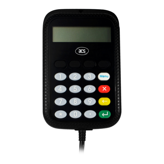
1.0. Introduction The APG8201-B2 is a portable and hand-held smart card device which supports PC-linked and standalone mode to perform various authentication applications. It features a built- in PIN-pad and a graphical LCD that supports multiple languages alpha-numeric characters. APG8201-B2... -
Page 6: Features
● Compliant with the following standards: ISO 7816 PC/SC PC/SC 2.0 Part 10 – Secure PIN Entry CCID RoHS 2 Microsoft® WHQL Uses an ACS-defined Android Library Page 6 of 48 www.acs.com APG8201-B2 – Reference Manual info@acs.com.hk www.acs.com.hk Version 1.00... -
Page 7: Supported Card Types
3.0. Supported Card Types The APG8201-B2 operates on MCU cards Class A (5 V) with T=0 and T=1 protocol in its main card slot. It also supports EEPROM microcontroller-based cards with internal programming voltage (VPP) generation and the following programming parameters transmitted in the ATR: ... -
Page 8: Smart Card Interface
4.0. Smart Card Interface The interface between the APG8201-B2 and the inserted smart card follows the specification of ISO 7816 Part 2 and 3 with certain restrictions and enhancements to increase the practical functionality of the APG8201-B2: Smart Card Power Supply VCC (C1) The current consumption of the inserted card must not be larger than 54 mA ... -
Page 9: Card Type Selection
The controlling computer always needs to select the card type through the proper command sent to the APG8201-B2 prior to activating the inserted card. For MCU-based cards, the reader allows to select the preferred protocol, T=0 or T=1. However, this selection is only accepted and carried out by the reader through the PPS when the card inserted in the reader supports both protocol types. -
Page 10: Usb Interface
The APG8201-B2 is connected to a computer through a USB, as specified in the USB Specification 2.0, working in full speed mode, i.e. 12 Mbps. In order for the APG8201-B2 to function properly through USB interface, either ACS proprietary device driver or ACS PC/SC device driver has to be installed. -
Page 11: Usb Communication Protocol (Ccid)
7.0. USB Communication Protocol (CCID) APG8201-B2 shall establish an interface to the host through the USB connection. A specification, namely CCID, has been released within the industry defining such a protocol for the USB chip-card interface devices. CCID covers all the protocols required for operating smart cards and PIN. The configurations and usage of USB endpoints on APG8201-B2 shall follow the CCID specification. -
Page 12: Pc_To_Rdr_Xfrblock
Identifies the slot number for this bSlot 00-FFh command Sequence number for command. bSeq 00-FFh Note: No related to the slot number and rolls over to 00h after FFh. Page 12 of 48 www.acs.com APG8201-B2 – Reference Manual info@acs.com.hk www.acs.com.hk Version 1.00... -
Page 13: Pc_To_Rdr_Setparameters
00-FFh Add 0 to 254 etu to the normal guardtime of 12etu. FFh is the same as 00h. bWaitingIntegerT0 00-FFh WI for T=0 used to define WWT Page 13 of 48 www.acs.com APG8201-B2 – Reference Manual info@acs.com.hk www.acs.com.hk Version 1.00... - Page 14 Size of negotiated IFSC Value = 00h if CCID doesn't support a bNadValue value other then the default value The response to this message is the RDR_to_PC_Parameters message. Page 14 of 48 www.acs.com APG8201-B2 – Reference Manual info@acs.com.hk www.acs.com.hk Version 1.00...
-
Page 15: Pc_To_Rdr_Escape
Display LCD Message Offset Field Size Value Description bcmdCode wcmdLength 0020h abRFU Reserved for future use Data from PC keyboard to show on the abData Example: bSendBuffer[0]=05h; bSendBuffer[1]=00h; Page 15 of 48 www.acs.com APG8201-B2 – Reference Manual info@acs.com.hk www.acs.com.hk Version 1.00... - Page 16 01: display char * Example: bSendBuffer[0]=06h; bSendBuffer[1]=00h; bSendBuffer[2]=06h; bSendBuffer[3]=00h; bSendBuffer[4]=00h; bSendBuffer[abData]=(00 08 04 01 00 00h) dwSendBufferLen=0Bh SCARDStatus = SCardControl( hSAM, SCARD_CTL_CODE(3500), bSendBuffer, dwSendBufferLen, bRecvBuffer, dwRecvBufferLen, &dwRecvBufferLen); Page 16 of 48 www.acs.com APG8201-B2 – Reference Manual info@acs.com.hk www.acs.com.hk Version 1.00...
- Page 17 Value Description bcmdCode wcmdLength 0000h abRFU Reserved for future use Example: bSendBuffer[0]=08h; bSendBuffer[1]=00h; bSendBuffer[2]=00h; bSendBuffer[3]=00h; bSendBuffer[4]=00h; dwSendBufferLen=05h SCARDStatus = SCardControl( hSAM, SCARD_CTL_CODE(3500), bSendBuffer, dwSendBufferLen, bRecvBuffer, dwRecvBufferLen, &dwRecvBufferLen); Page 17 of 48 www.acs.com APG8201-B2 – Reference Manual info@acs.com.hk www.acs.com.hk Version 1.00...
- Page 18 7.1.7.7. Set Reader Option Command Offset Field Size Value Description bcmdCode wcmdLength 0000h abRFU 0000h Bit define. Please refer to ReaderOptions Table 1. Example: bSendBuffer[0]=13h; bSendBuffer[1]=00h; bSendBuffer[2]=00h; Page 18 of 48 www.acs.com APG8201-B2 – Reference Manual info@acs.com.hk www.acs.com.hk Version 1.00...
-
Page 19: Pc_To_Rdr_Secure
00h: PIN Verification 01h: PIN Modification PIN Verification Data Structure or Byte abPINDataStructure array PIN Modification Data Structure 7.1.8.2. PIN Verification Data Structure Offset Field Size Value Description Page 19 of 48 www.acs.com APG8201-B2 – Reference Manual info@acs.com.hk www.acs.com.hk Version 1.00... -
Page 20: Version 1.00
APDU command bmPINLengthForm Allows the insertion of the PIN length in the APDU command Insertion position offset in byte for the bInsertionOffsetOld current PIN Page 20 of 48 www.acs.com APG8201-B2 – Reference Manual info@acs.com.hk www.acs.com.hk Version 1.00... -
Page 21: Version 1.00
Message index in the Reader message table (should be 00h or 01h). bMsgIndex1 The message is the prompt for the user to enter its new PIN if bConfirmPIN=00h or its current PIN. Page 21 of 48 www.acs.com APG8201-B2 – Reference Manual info@acs.com.hk www.acs.com.hk Version 1.00... -
Page 22: Version 1.00
Significant only if protocol in use is T=1. 28 or Byte abPINApdu 29 or APDU to send to the ICC array The response to this command message is the RDR_to_PC_DataBlock response message. Page 22 of 48 www.acs.com APG8201-B2 – Reference Manual info@acs.com.hk www.acs.com.hk Version 1.00... -
Page 23: Reader To Pc
01h = Clock stopped in state L 00h, 01h, bClockStatus 02h = Clock stopped in state H 02h, 03h 03h = Clock stopped in an unknown state All other values are RFU. Page 23 of 48 www.acs.com APG8201-B2 – Reference Manual info@acs.com.hk www.acs.com.hk Version 1.00... -
Page 24: Rdr_To_Pc_Parameters
7.2.3. RDR_to_PC_Parameters This message is sent by APG8201-B2 in response to the command message: PC_to_RDR_GetParameters, PC_to_RDR_ResetParameters and PC_to_RDR_SetParameters Offset Field Size Value Description bMessageType Size of abProtocolDataStructure field of dwLength this message Identifies the slot number for this bSlot command. Same value as in Bulk-OUT message. -
Page 25: Rdr_To_Pc_Escape
00-FEh Size of negotiated IFSC bNadValue 00-FFh Nad value used by CCID 7.2.4. RDR_to_PC_Escape This message is sent by APG8201-B2 in response to the command message PC_to_RDR_Escape. Offset Field Size Value Description bMessageType dwLength Size of abData field of this message... -
Page 26: Version 1.00
Description bRespType wcmdLength abRFU Reserved for Future Use 7.2.4.4. Read Key Offset Field Size Value Description bRespType wResLength abRFU 0000h Byte abData Data receive from Reader array Page 26 of 48 www.acs.com APG8201-B2 – Reference Manual info@acs.com.hk www.acs.com.hk Version 1.00... -
Page 27: Version 1.00
Value Description bRespType wResLength 0000h 0000h: SUCCESS abStatus 0001h: BAD_PARAMETER 7.2.4.10. Production Test Command Offset Field Size Value Description bRespType wResLength 0000h 0000h: SUCCESS abStatus 0001h: BAD_PARAMETER Page 27 of 48 www.acs.com APG8201-B2 – Reference Manual info@acs.com.hk www.acs.com.hk Version 1.00... -
Page 28: Version 1.00
7.2.4.11. Authentication Offset Field Size Value Description bRespType wResLength 0008h 0000h: SUCCESS abStatus 0001h: BAD_PARAMETER abData Eight bytes Authentication data Page 28 of 48 www.acs.com APG8201-B2 – Reference Manual info@acs.com.hk www.acs.com.hk Version 1.00... -
Page 29: Rdr_To_Pc_Notifyslotchange
7.2.5. RDR_to_PC_NotifySlotChange This message is sent whenever the APG8201-B2 detects a change in the insertion status of an ICC slot. Offset Field Size Value Description bMessageType This field is reported on byte granularity. The size is (2 bits * number of slots) rounded up to the nearest byte. -
Page 30: Pc-Linked Operation Mode
The user enters a pin and the reader sends the SECURE PIN VERIFY command to the card. Specific Status Codes SW1 SW2 Meaning 90 00h No error 63 Cxh Wrong PIN Page 30 of 48 www.acs.com APG8201-B2 – Reference Manual info@acs.com.hk www.acs.com.hk Version 1.00... -
Page 31: Secure Pin Modify
64 01h PIN entry is cancelled For current ACS smartcards, the number of PIN entry is set to 3. If wrong PIN is entered by the third attempt, the card is blocked. Note: No text is displayed for both correct and wrong PIN entry for APG8201-B2 Generic Reader. -
Page 32: Escape Commands
Get Key support “GET_KEY feature in PCSC part 10. Get Key (Host->Reader): 0A 00 06 00 00 60 01 01 85 00 00h Get Key (Reader->Host): 8A 00 02 00 00 31 31h Page 32 of 48 www.acs.com APG8201-B2 – Reference Manual info@acs.com.hk www.acs.com.hk Version 1.00... -
Page 33: Device Control
Feature Request control code and this API will return a list of supported features from the reader. In APG8201-B2, only Verify PIN Direct, Modify PIN Direct and IFD PIN Properties are supported. To use these features, you can get the control codes from the list. For more information, please refer to PC/SC 2.0 Specification Part 10. -
Page 34: Specific Scardcontrol
#define FEATURE_VERIFY_PIN_DIRECT 0x06 #define FEATURE_MODIFY_PIN_DIRECT 0x07 #define FEATURE_MCT_READERDIRECT 0x08 #define FEATURE_MCT_UNIVERSAL 0x09 #define FEATURE_IFD_PIN_PROP 0x0A #define FEATURE_ABORT 0x0B In APG8201-B2, the following features are supported: #define FEATURE_VERIFY_PIN_DIRECT 0x06 #define FEATURE_MODIFY_PIN_DIRECT 0x07 #define FEATURE_IFD_PIN_PROP 0x0A #define FEATURE_WRITE_DISPLAY 0x0F #define FEATURE_GET_KEY 0x10... -
Page 35: Feature_Verify_Pin_Direct
If the APG8201-B2 reader used supports PC/SC 2.0 Part 10, you will get the following data: 06 04 XX XX XX XX 07 04 XX XX XX XX 0A 04 XX XX XX XXh where, XX XX XX XXh is the control code for the feature. -
Page 36: Feature_Modify_Pin_Direct
6403h: User entered too short or too long PIN regarding MIN/MAX PIN Length. Note: APG8201-B2 will not return this status because it checks the PIN length during input. 6B80h: Invalid parameter in passed structure SW1SW2: Result from the card... -
Page 37: Version 1.00
Index of 1st prompting message bMsgIndex2 Index of 2nd prompting message bMsgIndex3 Index of 3rd prompting message T=1 I-block prologue field to use bTeoPrologue 000000h (fill with 00h). Page 37 of 48 www.acs.com APG8201-B2 – Reference Manual info@acs.com.hk www.acs.com.hk Version 1.00... -
Page 38: Feature_Ifd_Pin_Prop
6403h: User entered too short or too long PIN regarding MIN/MAX PIN Length. Note: APG8201-B2 will not return this status because it checks the PIN length during input. 6B80h: Invalid parameter in passed structure SW1SW2: Result from the card... -
Page 39: Ioctl_Smartcard_Get_Firmware_Version
OR operation together with the sixth element of the received buffer. Shift lpOutBuffer[4] by 8 bits Set OR operation with the shifted lpOutBuffer[4] and lpOutBuffer[5] value Input: hCard Reference value returned from SCardConnect Page 39 of 48 www.acs.com APG8201-B2 – Reference Manual info@acs.com.hk www.acs.com.hk Version 1.00... -
Page 40: Ioctl_Smartcard_Display_Lcd_Message
Pointer to a DWORD that receives the size, in bytes, of the data stored into the buffer pointed to by lpOutBuffer Offset Field Size Value Description 0000h SUCCESS abStatus 0001h BAD_PARAMETER Page 40 of 48 www.acs.com APG8201-B2 – Reference Manual info@acs.com.hk www.acs.com.hk Version 1.00... -
Page 41: Ioctl_Smartcard_Read_Key
Offset Field Size Value Description 0000h SUCCESS abStatus 0001h BAD_PARAMETER Maximum size reached Key [E] pressed bKeyReturnCondition Timeout occurred Key [C] pressed abNumericInputKeys 0-32 Page 41 of 48 www.acs.com APG8201-B2 – Reference Manual info@acs.com.hk www.acs.com.hk Version 1.00... -
Page 42: Feature_Ifd_Display_Properties
Valid value: 20h – FFh abLCDmessage nOutBufferSize lpBytesReturned Pointer to a DWORD that receives the size, in bytes, of the data stored into the buffer pointed to by lpOutBuffer Page 42 of 48 www.acs.com APG8201-B2 – Reference Manual info@acs.com.hk www.acs.com.hk Version 1.00... -
Page 43: Feature_Get_Key
“*” on LCD. 02h: No echo nOutBufferSize lpBytesReturned Pointer to a DWORD that receives the size, in bytes, of the data stored into the buffer pointed to by lpOutBuffer Page 43 of 48 www.acs.com APG8201-B2 – Reference Manual info@acs.com.hk www.acs.com.hk Version 1.00... -
Page 44: Appendix A. Set Bkeyreturncondition
Appendix A. Set bKeyReturnCondition bKeyReturnCondition OR Operand If Maximum PIN size is reached If APG8201-B2 device KEY_E is pressed If APG8201-B2 session TIMEOUT has reached If APG8201-B2 device KEY_C is pressed If APG8201-B2 device KEY_BACK is pressed If APG8201-B2 device KEY_FN is pressed Note: Set value to an OR Operation again the specific OR Operand. -
Page 45: Appendix B. Response Error Codes
Appendix B. Response Error Codes The following table summarizes the possible error code returned by the APG8201-B2 (CCID). Error Code Status 0001h BAD_PARAMETER 0083h SLOTERROR_LCDCOMMANDERROR 0084h SLOTERROR_WRONGCONFIRMPIN 0085h SLOTERROR_UNKNOWN_LCD 0086h SLOTERROR_MAXPINSIZE_EQUAL_ZERO 00EFh SLOTERROR_PIN_CANCELLED 00F0h SLOTERROR_PIN_TIMEOUT Page 45 of 48 www.acs.com APG8201-B2 –... -
Page 46: Appendix C. Bmformatstring Description
Bit 2 If 0h: Left justify data If 1h: Right justify data Bit wise for the PIN format type: 00h: binary Bit 1-0 01h: BCD 10h: ASCII Page 46 of 48 www.acs.com APG8201-B2 – Reference Manual info@acs.com.hk www.acs.com.hk Version 1.00... -
Page 47: Appendix D. Bmpinblockstring Description
0h, then the effective PIN length is not inserted in the APDU command) PIN length information: PIN block size in bytes after justification and Bit 3 - 0 formatting Page 47 of 48 www.acs.com APG8201-B2 – Reference Manual info@acs.com.hk www.acs.com.hk Version 1.00... -
Page 48: Appendix E. Bmpinlength Format
EMV is a registered trademark or trademark of EMVCo LLC in the United States and other countries. Microsoft, Windows and Windows Vista are registered trademarks of Microsoft Corporation in the United States and/or other countries. Page 48 of 48 www.acs.com APG8201-B2 – Reference Manual info@acs.com.hk www.acs.com.hk Version 1.00...
Need help?
Do you have a question about the APG8201-B2 and is the answer not in the manual?
Questions and answers