
Related Manuals for ACS ACR83 PINeasy


Summary of Contents for ACS ACR83 PINeasy
- Page 1 ACR83 PINeasy Reference Manual V1.06 Subject to change without prior notice info@acs.com.hk www.acs.com.hk...
-
Page 2: Table Of Contents
Modification Example 1 ......................36 12.10. Modification Example 2 ......................38 12.11. Modification Example 3 ......................40 12.12. Modification Example 4 ......................42 12.13. Modification Example 5 ......................45 Page 2 of 61 ACR83 – Reference Manual info@acs.com.hk www.acs.com.hk Version 1.06... - Page 3 Appendix D. Sample Code (PC/SC 2.0 Part 10) ............52 Appendix E. Set bKeyReturnCondition ................. 60 Appendix F. Response Error Codes ................61 List of Figures Figure 1 : PIN Verification and Modification Operation Flowchart ............22 Page 3 of 61 ACR83 – Reference Manual info@acs.com.hk www.acs.com.hk Version 1.06...
-
Page 4: Introduction
(for example, a PC) and a smart card. Different types of smart cards have different commands and communication protocols, and the ACR83 PINeasy establishes a uniform interface from the computer to the smart card for a wide variety of cards. -
Page 5: Features
Supports Secure PIN Entry (SPE) • EMV Level 1 Certified • Full-speed USB Interface (12 Mbps) • Compliant to the following standards: PC/SC Microsoft® WHQL CCID CE/FCC RoHS 2 Page 5 of 61 ACR83 – Reference Manual info@acs.com.hk www.acs.com.hk Version 1.06... -
Page 6: Supported Card Types
(TA2 present; bit b5 of TA2 must be 0) and when that the particular mode is not supported by the ACR83 PINeasy, the reader will reset the card to a negotiable mode. If the card cannot be set to negotiable mode, the reader will then reject the card. -
Page 7: Smart Card Interface
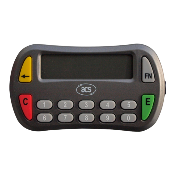
4.0. Smart Card Interface ACR83 PINeasy Smart Card Reader has a 14-key keypad and LCD display consisting of 2 rows with 16 characters dot matrix. 4.1. Smart Card Power Supply VCC (C1) The current consumption of the inserted card must not be higher than 100 mA. -
Page 8: Power Supply
The ACR83 (CCID) requires a voltage of 5 V DC, 100 mA regulated power supply. The ACR83 (CCID) gets the power from PC through the cable supplied along with each type of reader. Page 8 of 61 ACR83 – Reference Manual info@acs.com.hk www.acs.com.hk Version 1.06... -
Page 9: Usb Interface
Reference voltage level for power supply Table 1: USB Interface Wiring Note: ACR83 PINeasy is a PC/SC Device. In order for the ACR83 (CCID) to function properly through USB interface, an ACS PC/SC driver has to be installed. Please refer to the Device Driver Installation Guide for more details. -
Page 10: Communication Protocol
Does not support manual setting bNumDataRatesSupported of data rates Maximum IFSD supported by dwMaxIFSD 00000Feh ACR83 (CCID) for protocol T=1 is 254 ACR83 (CCID) does not support dwSynchProtocols 00000000h synchronous card Page 10 of 61 ACR83 – Reference Manual info@acs.com.hk www.acs.com.hk Version 1.06... - Page 11 Insignificant for TPDU level bClassGetResponse exchanges Insignificant for TPDU level bClassEnvelope exchanges wLCDLayout 0000h No LCD bPINSupport No PIN Verification Only one slot can be bMaxCCIDBusySlots simultaneously busy Page 11 of 61 ACR83 – Reference Manual info@acs.com.hk www.acs.com.hk Version 1.06...
-
Page 12: Pc/Sc Scardcontrol Application Programming Interface
#define CM_IOCTL_GET_FEATURE_REQUEST SCARD_CTL_CODE(3400) Note: Data is stored in little-endian form in which the LSB (Least Significant Byte) is first. Furthermore, SCardControl command must be declared in the source code. Page 12 of 61 ACR83 – Reference Manual info@acs.com.hk www.acs.com.hk Version 1.06... -
Page 13: Smart Card Device Ioctls
XX XX XX XXh is the control code for the feature. nOutBufferSize sizeof(ULONG) of IpOutBuffer lpBytesReturned pointer to a DWORD that receives the size, in bytes, of the data stored into the buffer pointed to by lpOutBuffer Page 13 of 61 ACR83 – Reference Manual info@acs.com.hk www.acs.com.hk Version 1.06... -
Page 14: Feature_Verify_Pin_Direct
T=1 I-block prologue field to use bTeoPrologue 000000h (fill with 00h) Length of data to be sent to the ulDataLength abData Data to send to the ICC nInBufferSize 19 + uLDataLength IpOutBuffer Page 14 of 61 ACR83 – Reference Manual info@acs.com.hk www.acs.com.hk Version 1.06... - Page 15 SW1SW2: Result from the card nOutBufferSize IpBytesReturned Pointer to a DWORD that receives the size, in bytes, of the data stored into the buffer pointed to by IpOutBuffer. Page 15 of 61 ACR83 – Reference Manual info@acs.com.hk www.acs.com.hk Version 1.06...
-
Page 16: Feature_Modify_Pin_Direct
If 0 = No current PIN entry requested. (In this case, the bInsertinoOffsetOld value must not be taken into account.) If 1 = Current PIN entry requested b2 – b7: RFU Page 16 of 61 ACR83 – Reference Manual info@acs.com.hk www.acs.com.hk Version 1.06... - Page 17 SW1SW2: Result from the card nOutBufferSize lpBytesReturned Pointer to a DWORD that receives the size, in bytes, of the data stored into the buffer pointed to by lpOutBuffer. Page 17 of 61 ACR83 – Reference Manual info@acs.com.hk www.acs.com.hk Version 1.06...
-
Page 18: Feature_Ifd_Pin_Prop
1 = IFD distinguishes bTimeOut from bTimeOut2 nOutBufferSize lpBytesReturned Pointer to a DWORD that receives the size, in bytes, of the data stored into the buffer pointed to by lpOutBuffer. Page 18 of 61 ACR83 – Reference Manual info@acs.com.hk www.acs.com.hk Version 1.06... -
Page 19: Ioctl_Smartcard_Get_Firmware_Version
Shift lpOutBuffer[4] by 8 bits Set OR operation with the shifted lpOutBuffer[4] and lpOutBuffer[5] value Input: hCard Reference value returned from SCardConnect dwControlCode IOCTL_SMARTCARD_GET_FIRMWARE_VERSION Output: lpOutBuffer Output value of command Page 19 of 61 ACR83 – Reference Manual info@acs.com.hk www.acs.com.hk Version 1.06... -
Page 20: Ioctl_Smartcard_Display_Lcd_Message
IOCTL_SMARTCARD_READ_KEY The IOCTL_SMARTCARD_READ_KEY enables Read Key command. Input: hCard Reference value returned from SCardConnect dwControlCode IOCTL_SMARTCARD_READ_KEY lpInBuffer Set value for Display LCD message option nInBufferSize sizeof(ULONG) of lpInBuffer Page 20 of 61 ACR83 – Reference Manual info@acs.com.hk www.acs.com.hk Version 1.06... - Page 21 Offset Field Size Value Description 0000h SUCCESS abStatus 0001h BAD_PARAMETER Maximum size reached Key [E] pressed bKeyReturnCondition Timeout occurred Key [C] pressed abNumericInputKeys 0-32 Page 21 of 61 ACR83 – Reference Manual info@acs.com.hk www.acs.com.hk Version 1.06...
-
Page 22: Operation Flow For Pin Verification And Modification (Pc/Sc 2.0 Part 10)
In ACR83, only Verify PIN Direct, Modify PIN Direct and IFD PIN Properties are supported. To use these features, you can get the control codes from the list. For more information, please refer to PC/SC 2.0 Specification Part 10. Page 22 of 61 ACR83 – Reference Manual info@acs.com.hk www.acs.com.hk Version 1.06... -
Page 23: Ccid Spe Data Structure
The Modes setting is based on CCID abPINOperationDataStructure. For more information, please refer to CCID specification 6.1.11.1. bPINOperation: 00h: PIN Verification 01h: PIN Modification Any other values will not be supported by ACR83. Page 23 of 61 ACR83 – Reference Manual info@acs.com.hk www.acs.com.hk Version 1.06... -
Page 24: Pin Verification Data Structure
XX: (SpePinMin) Minimum PIN Size YY: (SpePinMax) Maximum PIN Size bNumberMessage: 00h: No message display in LCD 01h: Display one message: LCD will display “Enter PIN:” FFh: Default value equal to 01h Page 24 of 61 ACR83 – Reference Manual info@acs.com.hk www.acs.com.hk Version 1.06... -
Page 25: Error Checking (Bit)
SpePinMin must be equal or larger than 1 Verification system unit is byte. Command Header Offset SpePINPos SpePINLen APDU Command APDU Offset SpePINPos Header Length Offset Not used CLA INS P1 P2 SpePINSize SpePINLenPos field Page 25 of 61 ACR83 – Reference Manual info@acs.com.hk www.acs.com.hk Version 1.06... -
Page 26: Verification Example 1
SpePinPos=7 bits because bmFormatString bit 7 = 0 SpeLeftRight=Left SpePINTyp=BCD bmPINBlockString=49h SpePINSize=4 bits SpePINLen=9 bytes bmPINLengthFormat=02h SpePINLenPos=2 bits wPINMaxExtraDigit=010Ah SpePinMax=0Ah SpePinMin=01h PIN Input = 1 2 3 4 5 6 7 8 0 Page 26 of 61 ACR83 – Reference Manual info@acs.com.hk www.acs.com.hk Version 1.06... -
Page 27: Version 1.06
00 20 00 01 09 66 24 68 AC F0 10 30 30 30h If arrangement is Right: bmFormatString change to=3Dh 00 20 00 01 09 67 30 30 30 31 23 45 67 80h Page 27 of 61 ACR83 – Reference Manual info@acs.com.hk www.acs.com.hk Version 1.06... -
Page 28: Verification Example 2
0001 0010 0011 0100 0101 bit format) 0 0101 0011 0000 0011 0000 0011 0000 0011 0000 0011 Original 0000 0011 0000 Input PIN 0 0010 0100 0110 1000 101 Page 28 of 61 ACR83 – Reference Manual info@acs.com.hk www.acs.com.hk Version 1.06... -
Page 29: Verification Example 3
After Lc (09h), the first 1 byte 57h is control character. bmFormatString = 89h SpePinPos = 1 byte because bmFormatString bit 7 = 1 SpeLeftRight = Left SpePINTyp = BCD bmPINBlockString = 48h Page 29 of 61 ACR83 – Reference Manual info@acs.com.hk www.acs.com.hk Version 1.06... -
Page 30: Version 1.06
00 20 00 01 09 57 30 30 30 30 30 30 30 30 Input 12 34 56 78 0 Result PIN 00 20 00 01 09 59 12 34 56 78 00 30 30 30 Page 30 of 61 ACR83 – Reference Manual info@acs.com.hk www.acs.com.hk Version 1.06... -
Page 31: Version 1.06
59 12 34 56 78 00 30 30 30h If arrangement is Right: bmFormatString change to = 8Dh 00 20 00 01 08 30 30 30 31 23 45 67 80h Page 31 of 61 ACR83 – Reference Manual info@acs.com.hk www.acs.com.hk Version 1.06... -
Page 32: Pin Modification Data Structure
Bit4: 0: indicates if the SpePINLenPos is in bit or byte unit bInsertionOffsetOld (SpeOffsetOld): insertion position offset in byte for the current PIN bInsertionOffsetNew (SpeOffsetNew): insertion position offset in byte for the new PIN Page 32 of 61 ACR83 – Reference Manual info@acs.com.hk www.acs.com.hk Version 1.06... -
Page 33: Modification (Bit) Bconfirmpin Bit1=0
System unit is bit. APDU Command SpeOffsetNew SpePINLen APDU APDU Header Maybe not Offset SpePINPos Not used Offset CLA INS P1 P2 Exists SpePINSize field/Does not SpePINLenPos exist Page 33 of 61 ACR83 – Reference Manual info@acs.com.hk www.acs.com.hk Version 1.06... -
Page 34: Modification (Bit) Bconfirmpin Bit1=0 Data Structure Error Checking
System unit is bit. APDU Command SpeOffsetOld SpePINLen APDU APDU Maybe not Offset SpePINPos Old PIN Header CLA INS Offset Not used Exist SpePINSize Old PIN P1 P2 SpePINLenPos field Page 34 of 61 ACR83 – Reference Manual info@acs.com.hk www.acs.com.hk Version 1.06... -
Page 35: Modification (Bit) Bconfirmpin Bit1=1 Data Structure Error Checking
CLA INS P1 P2 Exist SpePINSize Old PIN SpePINLenPos field SpeOffsetNew Offset SpePINPos SpePINLen Maybe not Offset SpePINPos New PIN Offset Exists SpePINSize Not used field New PIN SpePINLenPos Page 35 of 61 ACR83 – Reference Manual info@acs.com.hk www.acs.com.hk Version 1.06... -
Page 36: Modification (Byte) Bconfirmpin Bit1=1 Data Structure Error Checking
= 00h (if bConfirmPIN = 00h, the bNumberMessage must equal to 01h, 00h) Enter the New PIN once. bmFormatString = 39h SpePinPos = 7 bits because bmFormatString bit 7 = 0 SpeLeftRight = Left SpePINTyp = BCD Page 36 of 61 ACR83 – Reference Manual info@acs.com.hk www.acs.com.hk Version 1.06... -
Page 37: Version 1.06
Input 9 digits 00 24 00 01 01=0101011 1001 (bits) 1 (bit)=0101011 00 24 00 01 0110011 (1001 replace original 0101011) The PIN management is BCD and left arrangement. Page 37 of 61 ACR83 – Reference Manual info@acs.com.hk www.acs.com.hk Version 1.06... -
Page 38: Modification Example 2
= 39h SpePinPos = 7 bits because bmFormatString bit 7 = 0 SpeLeftRight = Left SpePINTyp = BCD bmPINBlockString = 49h SpePINSize = 4 bits SpePINLen = 9 bytes Page 38 of 61 ACR83 – Reference Manual info@acs.com.hk www.acs.com.hk Version 1.06... -
Page 39: Version 1.06
Lc 00 24 00 01 01=0101011 1001(bits) 1 (bit)=0101011 00 24 00 01 0110011 (1001 replace original 0101011) The PIN management is BCD and left arrangement. Page 39 of 61 ACR83 – Reference Manual info@acs.com.hk www.acs.com.hk Version 1.06... -
Page 40: Modification Example 3
1. Lc must be equal to SpePINLen + SpePINPos + SpeOffsetNew 2. SpePINPos must be equal or larger than SpePINLenPos + SpePINSize 3. SpePINLen – SpePINPos must be larger or equal to SpePinMax (if BCD, need multiple 4) Page 40 of 61 ACR83 – Reference Manual info@acs.com.hk www.acs.com.hk Version 1.06... -
Page 41: Version 1.06
Point 2: SpePINPos (1 Byte) >= SpePinLenPos (4 bits) + SpePINSize (4 bits) • Point 3: SpePINLen (9) – SpePinPos (1 Byte) >=[SpePinMax (0Ah) * 4 bits(BCD)] = 5 bytes : 8 bytes >=5 bytes Page 41 of 61 ACR83 – Reference Manual info@acs.com.hk www.acs.com.hk Version 1.06... -
Page 42: Modification Example 4
System unit is bit. APDU Command SpeOffsetOld SpePINLen APDU APDU Header Maybe not Offset SpePINPos Old PIN Offset Not used SpePINSize CLA INS P1 P2 Exists Old PIN SpePINLenPos field Page 42 of 61 ACR83 – Reference Manual info@acs.com.hk www.acs.com.hk Version 1.06... -
Page 43: Version 1.06
SpePINLenPos = 4 bits wPINMaxExtraDigit = 010Ah SpePinMax = 0Ah SpePinMin = 01h bInsertionOffsetNew(SpeOffsetNew) = 0Ah SpeOffsetNew = 0Ah byte bInsertionOffsetOld (SpeOffsetOld) = 01h SpeOffsetOld = 01h byte Page 43 of 61 ACR83 – Reference Manual info@acs.com.hk www.acs.com.hk Version 1.06... -
Page 44: Version 1.06
Input 10 digits New PIN relative to Lc 00=00000011 1010 (bits) New PIN 00001010 (1010 replace original 00000011) New PIN First, handle the old PIN. Old PIN (Byte) Page 44 of 61 ACR83 – Reference Manual info@acs.com.hk www.acs.com.hk Version 1.06... -
Page 45: Modification Example 5
SpePINLen – SpePINPos must be larger or equal to SpePinMax (if BCD, need multiple 4) • SpePinMax must be equal or larger than SpePinMin • SpePinMax cannot be larger than 16 digits because LCD one row only have 16 digits Page 45 of 61 ACR83 – Reference Manual info@acs.com.hk www.acs.com.hk Version 1.06... -
Page 46: Version 1.06
• Point 2: SpeOffsetNew (0Ah) >= SpeOffsetOld (1) + SpePINLen (6) + SpePinPos (2) • Point 3: SpePINPos (2 Bytes) >= SpePinLenPos (1 Byte) + SpePINSize (4 bits) Page 46 of 61 ACR83 – Reference Manual info@acs.com.hk www.acs.com.hk Version 1.06... -
Page 47: Version 1.06
12 34 56 78 90 00 24 00 01 12 2F 0A 66 12 34 56 30 30 30 2E FB A7 12 34 Result PIN 56 78 90 Page 47 of 61 ACR83 – Reference Manual info@acs.com.hk www.acs.com.hk Version 1.06... -
Page 48: Version 1.06
The whole APDU after the format will be: 00 24 00 01 12 2F 0A 66 12 34 56 30 30 30 2E FB A7 12 34 56 78 90 Page 48 of 61 ACR83 – Reference Manual info@acs.com.hk www.acs.com.hk Version 1.06... -
Page 49: Appendix A. Bmformatstring Description
Bit mask for the PIN justification: Bit 2 If 0h: Left justify data If 1h: Right justify data Bit wise for the PIN format type: 00h: binary Bit 1-0 01h: BCD 10h: ASCII Page 49 of 61 ACR83 – Reference Manual info@acs.com.hk www.acs.com.hk Version 1.06... -
Page 50: Appendix B. Bmpinblockstring Description
APDU command) PIN length information: PIN block size in bytes after justification and Bit 3 - 0 formatting Page 50 of 61 ACR83 – Reference Manual info@acs.com.hk www.acs.com.hk Version 1.06... -
Page 51: Appendix C. Bmpinlengthformat
If 1h: the system units are bytes Indicates the PIN length position in the APDU command according to Bit 3 - 0 the previous parameters (maximum 1111 for 15 system units) Page 51 of 61 ACR83 – Reference Manual info@acs.com.hk www.acs.com.hk Version 1.06... -
Page 52: Appendix D. Sample Code (Pc/Sc 2.0 Part 10)
BYTE bmPINBlockString; BYTE bmPINLengthFormat; BYTE bInsertionOffsetOld; BYTE bInsertionOffsetNew; USHORT wPINMaxExtraDigit; BYTE bConfirmPIN; BYTE bEntryValidationCondition; BYTE bNumberMessage; USHORT wLangId; BYTE bMsgIndex1; BYTE bMsgIndex2; BYTE bMsgIndex3; BYTE bTeoPrologue[3]; ULONG ulDataLength; Page 52 of 61 ACR83 – Reference Manual info@acs.com.hk www.acs.com.hk Version 1.06... -
Page 53: Version 1.06
// Advance to the next value pReader = pReader + strlen(pReader) + 1; numReaders++; // Allocate reader name readerName = new char*[numReaders]; if (readerName == NULL) printf("Error: not enough memory\n"); Page 53 of 61 ACR83 – Reference Manual info@acs.com.hk www.acs.com.hk Version 1.06... -
Page 54: Version 1.06
(lReturn != SCARD_S_SUCCESS) printf("Error: SCardConnect failed with error 0x%08x\n", lReturn); else // Get feature request printf("Getting feature request...\n"); dwRecvBufferLen = sizeof(bRecvBuffer); lReturn = SCardControl(hCard, CM_IOCTL_GET_FEATURE_REQUEST, NULL, 0, bRecvBuffer, dwRecvBufferLen, &dwRecvBufferLen); Page 54 of 61 ACR83 – Reference Manual info@acs.com.hk www.acs.com.hk Version 1.06... -
Page 55: Version 1.06
// Send card command for PIN verification (ACOS3) dwSendBufferLen = 13; memcpy(bSendBuffer, "\x80\x20\x06\x00\x08\xFF\xFF\xFF\xFF\xFF\xFF\xFF\xFF", dwSendBufferLen); // Create PIN verify structure PPIN_VERIFY_STRUCTURE pPinVerify (PPIN_VERIFY_STRUCTURE) BYTE[sizeof(PIN_VERIFY_STRUCTURE) - 1 + dwSendBufferLen]; if (pPinVerify == NULL) Page 55 of 61 ACR83 – Reference Manual info@acs.com.hk www.acs.com.hk Version 1.06... -
Page 56: Version 1.06
BYTE[sizeof(PIN_MODIFY_STRUCTURE) - 1 + dwSendBufferLen]; if (pPinModify == NULL) printf("Error: not enough memory\n"); exit(1); // Initialize PIN modify structure (ACOS3) pPinModify->bTimeOut = 0; pPinModify->bTimeOut2 = 0; pPinModify->bmFormatString = 0; pPinModify->bmPINBlockString = 0x08; Page 56 of 61 ACR83 – Reference Manual info@acs.com.hk www.acs.com.hk Version 1.06... -
Page 57: Version 1.06
&dwRecvBufferLen); if (lReturn != SCARD_S_SUCCESS) printf("Error: SCardControl failed with error 0x%08x\n", lReturn); else printf("Response: "); for (i = 0; i < dwRecvBufferLen; i++) printf("%02X ", bRecvBuffer[i]); printf("\n"); Page 57 of 61 ACR83 – Reference Manual info@acs.com.hk www.acs.com.hk Version 1.06... -
Page 58: Version 1.06
= 0; len = 0; if (dwNumBytesReturned >= 4) len = dwNumBytesReturned - 3; memcpy(keyString, bOutputBuffer + 3, len); // Set the last NULL character keyString[len] = '\0'; Page 58 of 61 ACR83 – Reference Manual info@acs.com.hk www.acs.com.hk Version 1.06... -
Page 59: Version 1.06
(lReturn != SCARD_S_SUCCESS) printf("Error: SCardReleaseContext failed with error 0x%08x\n", lReturn); // Deallocate reader name for (i = 0; i < numReaders; i++) delete [] readerName[i]; delete readerName; return 0;} Page 59 of 61 ACR83 – Reference Manual info@acs.com.hk www.acs.com.hk Version 1.06... -
Page 60: Appendix E. Set Bkeyreturncondition
If ACR83 device KEY_C is pressed If ACR83 device KEY_BACK is pressed If ACR83 device KEY_FN is pressed Note: Set value to an OR Operation again the specific OR Operand. Page 60 of 61 ACR83 – Reference Manual info@acs.com.hk www.acs.com.hk Version 1.06... -
Page 61: Appendix F. Response Error Codes
BAD_PARAMETER 0083h SLOTERROR_LCDCOMMANDERROR 0084h SLOTERROR_WRONGCONFIRMPIN 0085h SLOTERROR_UNKNOWN_LCD 0086h SLOTERROR_MAXPINSIZE_EQUAL_ZERO 00EFh SLOTERROR_PIN_CANCELLED 00F0h SLOTERROR_PIN_TIMEOUT Microsoft is a registered trademark of Microsoft Corporation in the United States and/or other countries. Page 61 of 61 ACR83 – Reference Manual info@acs.com.hk www.acs.com.hk Version 1.06...
Need help?
Do you have a question about the ACR83 PINeasy and is the answer not in the manual?
Questions and answers