Table of Contents
Advertisement
Quick Links
CONTENTS
SAFETY CONSIDERATIONS.......................................1
GENERAL..................................................................1
DIMENSIONAL DRAWINGS.......................................... 2
INSTALLATION CONSIDERATIONS.............................4
INSTALLATION..........................................................4
SETTING NETWORK ADDRESS.......................................6
BASIC CONFIGURATION....................................................6
•
LOGIN........................................................................6
•
BRAND CHOICE.......................................................7
•
AUTO SEARCH.........................................................7
SAFETY CONSIDERATIONS
Read and follow manufacturer instructions carefully.
Follow all local electrical codes during installation. All wiring
must conform to local and national electrical codes. Improper
wiring or installation may damage thermostat.
Understand the signal words - DANGER, WARNING,
and CAUTION. DANGER identifies the most serious hazards
which will result in severe personal injury or death.
WARNING signifies hazards that could result in personal
injury or death. CAUTION is used to identify unsafe practices,
which would result in minor personal injury or product and
property damage.
Recognize safety information. This
symbol (
). When this symbol is displayed on the unit and in
instructions or manuals, be alert to the potential for personal
injury. Installing, starting up, and servicing equipment can be
hazardous due to system pressure, electrical components, and
equipment location.
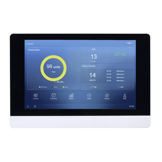
GENERAL
The VRF (variable refrigerant flow) touch screen central
controller is a wall-mounted, low-voltage controller that
provides site-level control of multiple VRF systems. The
controller allows central management of mode, setpoint,
and scheduling of indoor units (IDUs).
The touch screen central controller is available for use
with the VRF (variable refrigerant flow) outdoor units /
systems listed in Table 1.
NOTES:
1. Changes or modifications of this product not expressly
approved by the party responsible for compliance could
void the user's authority to operate the equipment.
2. This equipment has been tested and found to comply with
the limits for a Class A digital device, pursuant to Part 15
of the FCC Rules. These limits are designed to provide
reasonable protection against harmful interference when
the equipment is operated in a commercial environment.
This equipment generates, uses, and can radiate radio
Manufacturer reserves the right to discontinue, or change at any time, specifications or designs without notice and without incurring obligations.
Catalog No. 17-40VM9006-01
Touch Screen Central Controller Accessory
Installation Instructions
Part Number 40VM900006
For Commercial Use Only
Page
Printed in China
Form 40VM-5SIR1
VRF (Variable Refrigerant Flow) System
accordance with the instruction manual, may cause
harmful interference to radio communications. Operation
of this equipment in a residential area is likely to cause
harmful interference-in which case the user will be
required to correct the interference at their own expense.
This equipment should be installed and operated with a
minimum distance of 20 centimeters between the radiator
and your body.
Table 1: Touch Screen Central Controller
Accessory Usage
UNIT
38VMAR Heat Recovery System 072,096,120,144, 168, 192, 216,
38VMAH Heat Pump System
Table 2: Components shipped with Unit
NAME
IMAGE
Mounting
Box
Mounting
Plate
Screws
(Short)
Screws
Washers
Table 3: Specifications
Power Supply
(field provided)
Current Requirement
Dimensions
(inches)
Total Weight
Number of X/Y
Bus Lines
Max. Refrigerant
Systems/IDUs
per Line
Pg 1
38VM/40VM Series
SIZES
240, 264, 288, 312, 336
036, 048, 060, 072, 096, 120,
144, 168, 192, 216, 240, 264,
288, 312, 336, 360, 384, 408,
432
QTY
FUNCTION
1
Plastic mounting enclosure
Steel plate connecting
1
controller to front of Mounting
Box
Used to Install Mounting Box
6
to Wall
Used to install Mounting Plate
4
on Mounting Box
Used to install Mounting Plate
on Mounting Box
8
(2 extra washers for fine
adjustment if wall is uneven)
Rated Voltage
24VAC, 60 Hz
H
W
10-7/8
D
Touch Screen Controller, Mounting Box,
Mounting Plate, & Screws: 2 lbs 12 oz
6
8/64
09-17
Replaces: 40VM-5SI
1A
7-3/8
1-1/4
Advertisement
Table of Contents

Related Manuals for Carrier 40VM900006


Summary of Contents for Carrier 40VM900006
-
Page 1: Table Of Contents
38VM/40VM Series VRF (Variable Refrigerant Flow) System Touch Screen Central Controller Accessory Installation Instructions Part Number 40VM900006 For Commercial Use Only CONTENTS accordance with the instruction manual, may cause harmful interference to radio communications. Operation of this equipment in a residential area is likely to cause... -
Page 2: Dimensional Drawings
DIMENSIONAL DRAWING 1-1/4 10-7/8 Fig. 1 — Dimensions... - Page 3 · · · · · · · X4 E Y4 X5 E Y5 X6 E Y6 X1 E Y1 X2 E Y2 X3 E Y3 Fig. 2 — Connection Description Table 4 — Connection Description NAME FUNCTION 24VAC power 24VAC common X conductor, X/Y bus (no 1-6) Y conductor, X/Y bus (no 1-6) Shield conductor, X/Y bus (no 1-6)
-
Page 4: Installation Considerations
INSTALLATION CONSIDERATIONS 3. For flush-mount installation, provide a 10-1/4" by 6-5/8" opening in drywall or mounting surface to accommodate The controller should be mounted: the mounting box. • at a location that allows easy access CAUTION • on a section of wall without water or drainage pipes The controller should NOT be mounted: Over-tightening the screw will cause deformation to •... - Page 5 7. Wire the Controller: Control Wire: Use 16 to 20 AWG (American Wire Gage), stranded twisted pair shielded 2-core wiring (copper wire). The controller has 6 central control bus (X/Y) lines. Each line can support up to 8 refrigerant systems and 64 indoor units, maximum.
-
Page 6: Setting Network Address
8. Install the Controller: After wiring, install the controller (1) onto the mounting plate. Position the holes over the metal hooks and slide down to lock into place. See Figure 7. wall BLACK w a l l BLACK GRAY MAIN BOARD BLUE BLACK Fig. -
Page 7: Brand Choice
Brand Choice — One of the following Home Screens will display depending on whether the user chose Bryant or Carrier: 1. Start up the Touch Screen Central Controller. The following splash screen will briefly be displayed: The following screen will be displayed: 5. - Page 8 Refer to the User Manual for additional details on operation. Manufacturer reserves the right to discontinue, or change at any time, specifications or designs without notice and without incurring obligations. Catalog No. 17-40VM9006-01 Printed in China Form 40VM-5SIR1 Pg 8 09-17 Replaces: 40VM-5SI...
Need help?
Do you have a question about the 40VM900006 and is the answer not in the manual?
Questions and answers