Sign In
Upload
Download
Table of Contents
Contents
Add to my manuals
Delete from my manuals
Share
URL of this page:
HTML Link:
Bookmark this page
Add
Manual will be automatically added to "My Manuals"
Print this page
×
Bookmark added
×
Added to my manuals
Manuals
Brands
Curtis Manuals
Brewing Systems
D500GT12A000
User manual
Curtis D500GT12A000 User Manual
G3 d500 series, airpot coffee brewing system
Hide thumbs
Also See for D500GT12A000
:
User manual
(35 pages)
1
Table Of Contents
2
3
4
5
6
7
8
9
10
11
12
13
14
15
16
17
18
19
20
21
22
23
24
25
26
27
28
29
30
31
32
page
of
32
Go
/
32
Contents
Table of Contents
Bookmarks
Advertisement
Table of Contents
1
Table of Contents
2
Fs30
3
Is2
4
Ii2
5
Ii35
6
Oi23
7
Ci1
8
Ci9
9
Ip54
10
Ip21
11
Ip24
12
Ip55
13
Es55
14
Es57
15
Ec4
Download this manual
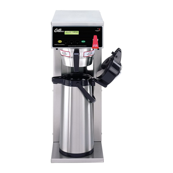
USER GUIDE
G3 D500 Series
Airpot Coffee Brewing System
READ AND SAVE THESE INSTRUCTIONS
NOTICE TO INSTALLER: Please leave this booklet with the machine.
122717B
FC30 - D500, FRONT COVER
F-10029 revA
Table of
Contents
Previous
Page
Next
Page
1
2
3
4
5
Advertisement
Table of Contents
Need help?
Do you have a question about the D500GT12A000 and is the answer not in the manual?
Ask a question
Questions and answers
Related Manuals for Curtis D500GT12A000
Coffee Maker Curtis G3 D500 Series User Manual
Airpot coffee brewing system (35 pages)
Brewing Systems Curtis D500GT Service Manual
Airpot brewer (9 pages)
Brewing Systems Curtis D500GTH12A000 User Manual
G3 d500 series, airpot coffee brewing system (32 pages)
Brewing Systems Curtis D500GT63A000 User Manual
G3 d500 series, airpot coffee brewing system (32 pages)
Brewing Systems Curtis D500GT30A000 User Manual
G3 d500 series, airpot coffee brewing system (32 pages)
Brewing Systems Curtis ALPHA-D Diagnostics Manual
(28 pages)
Brewing Systems Curtis D60GT12 Series User Manual
Thermal decanter coffee brewing system (31 pages)
Brewing Systems Curtis D60GT12A000 User Manual
Thermal decanter coffee brewing system (31 pages)
Brewing Systems Curtis G3 ThermoPro TP2T10A3100 User Manual
1.5 gallon coffee brewing system (44 pages)
Brewing Systems Curtis G3 User Manual
Digital high volume combo brewers (33 pages)
Brewing Systems Curtis ThermoPro G3 Series User Manual
1.5 gallon coffee brewing system (43 pages)
Brewing Systems Curtis GEMTIF10A1000 Troubleshooting Manual
G3 gemini intellifresh series (8 pages)
Brewing Systems Curtis G4 Series User Manual
High volume combo brewers (35 pages)
Brewing Systems Curtis 3000 Series Instructions
(2 pages)
Brewing Systems Curtis RTB User Manual
G3 digital iced tea brewing system with rotating brew basket (34 pages)
Brewing Systems Curtis Gem-230A Instructions
Satellite (4 pages)
This manual is also suitable for:
D500gt63a000
D500gth12a000
D500gt30a000
D500gth63a000
Table of Contents
Print
Rename the bookmark
Delete bookmark?
Delete from my manuals?
Login
Sign In
OR
Sign in with Facebook
Sign in with Google
Upload manual
Upload from disk
Upload from URL


Need help?
Do you have a question about the D500GT12A000 and is the answer not in the manual?
Questions and answers