Table of Contents
Advertisement
Quick Links
Advertisement
Table of Contents

Related Manuals for Draytek VigorSwitch V1281


Summary of Contents for Draytek VigorSwitch V1281
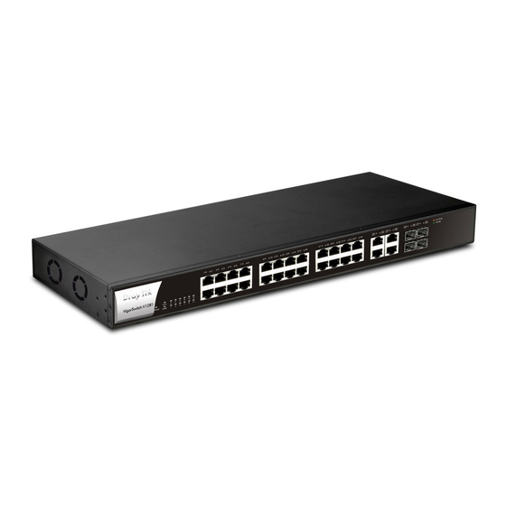
- Page 2 VigorSwitch V1281 24 Ports + 4 Combo UTP/SFP Ports A/V Video Switch User’s Guide Version: 1.0 Firmware Version: V2.3.0 (For future update, please visit DrayTek web site) Date: Jun 2018 VigorSwitch V1281 User Guide...
- Page 3 When you dispose of the switch, please follow local regulations. Warranty DrayTek Corp. warrants to the original end user (purchaser) that the router will be free from any defects in workmanship or materials for a period of two (2) years from the date of purchase from a DrayTek authorized dealer in the UK/Ireland.
-
Page 4: Regulatory Information
You should keep the Firmware & Tools Updates firmware/software of all equipment up to date. Please consult the DrayTek web site for more information on newest firmware, tools and documents: www.draytek.co.uk (For UK/Ireland) VigorSwitch V1281 User Guide... -
Page 5: Table Of Contents
III-1-2-3 [IGMP Static Group]..................37 III-1-2-4 [IGMP Group Table]..................38 III-1-2-5 [IGMP Router Table]..................39 III-2 [SNMP]............................. 40 III-2-1 [View].......................... 41 III-2-2 [Group]........................42 III-2-3 [Community]........................ 44 III-2-4 [User].......................... 45 III-2-5 [Engine ID]........................47 III-2-5-1 [Local Engine ID]..................... 47 VigorSwitch V1281 User Guide... - Page 6 III-9 [Factory Default]........................64 III-10 [Reboot]..........................65 Part IV Troubleshooting....................66 IV-1 [Diagnostics].......................... 67 IV-1-1 [Cable Diagnostics]....................67 IV-1-2 [Ping Test]........................68 IV-1-3 [SysLog]........................69 IV-1-3-1 [SysLog Explorer]................... 69 IV-1-3-2 [SysLog Settings].................... 70 IV-2 Contacting DrayTek........................ 73 VigorSwitch V1281 User Guide...
-
Page 7: Part I Introduction
Part I Introduction Part I Introduction VigorSwitch V1281 User Guide... -
Page 8: I-1 Introduction
I-1 Introduction I-1 Introduction The VigorSwitch V1281 is a Gigabit Ethernet switch optimized for the switching of A/V signals over IP. The V1281 is designed with an intuitive and easy to use interface for both installers and the end users who will be using the product. - Page 9 Environment: Operation Temperature: 0°C~40°C Storage Temperature: -10°C~70°C Dimensions: 441 x 270 x 45 mm (W x D x H). Rack mountable: 1U. Brackets included. Power: 110-250VAC Weight: 4.4Kg (excluding SFP modules/cables) VigorSwitch V1281 User Guide...
-
Page 10: I-2 Package Contents
If any of these items is missing or damaged when you receive the product, please immediately contact your supplier. You will also need HDMI-to-IP extenders/convertors – one for each A/V source or output. These are not supplied with the VigorSwitch (see Section I-3 for more information). VigorSwitch V1281 User Guide... -
Page 11: I-3 Led Indicators And Connectors
RJ-45 or SFP Ports 25 ~ 28 45 ports. If you use, for example, Port 25 as RJ-45, you cannot use the corresponding SFP Port 25 and vice- versa. Power inlet: AC 100~240V/AC, 50/60Hz. IEC/C24 Socket on Rear VigorSwitch V1281 User Guide... -
Page 12: Principles Of Operation
Principles of Operation Principles of Operation Although you may have used DrayTek switches for regular networking applications previously, the V1281 is different because it’s designed for switching A/V. Sources and Outputs Throughout this Quick Setup Guide and also within the V1281’s admin interface we will refer to sources and outputs. - Page 13 CAT5/CAT6 cable, but using a proprietary method, and not IP or Ethernet. That type of device will not work with the VigorSwitch V1281 and may even cause damage so please be sure that the device you connect uses IP and Ethernet (10/100/1000BaseT). Any additional...
-
Page 14: Vigorswitch Installation
Physical Installation – Rack or Desktop Fitting The VigorSwitch V1281 can sit on a desk or shelf; please fit the rubber feet (supplied) only if you will be using it in that way. If you will be mounting the switch in a standard 19” rack, attach the rack mount ‘ears’... -
Page 15: Topology And Hardware Installation
Topology and Hardware Installation Topology and Hardware Installation Installing and configuring your VigorSwitch V1281 should be very straightforward if you plan carefully and are clear about your network/AV topology. Before starting, ensure that you know how many sources (Satellite Receivers, Blu-Ray, DVD, STB etc.) you will have and how many outputs (screens/projectors) you’ll be feeding to. -
Page 16: Device Connection
Connect an HDMI-to-IP sender unit to each source device (Set-top boxes, DVD players etc.). The sender units will also need power (not shown). Connect the Ethernet end of the sender to your VigorSwitch V1281. In the example photo below, we have used two satellite TV receivers as the sources:... - Page 17 Connect an HDMI-to-IP receiver unit to all output devices (TVs or Projectors) and connect an Ethernet cable from the receiver unit to the VigorSwitch V1281 (via your structured cabling or RJ-45 sockets around the building etc.). Receiver units will also need power (not...
-
Page 18: I-6 Initial Switch Configuration
PC with a keyboard/mouse. If you connected the VigorSwitch V1281 to your network (see earlier), the V1281 will obtain its own IP address from your network DHCP server (your router or other device providing DHCP). -
Page 19: I-6-2 Access The Vigorswitch's Web Interface (Gui)
Remember your new admin password – there is no way to recover it or access the switch otherwise. After logging in, the main dashboard of the VigorSwitch V1281 will be shown: VigorSwitch V1281 User Guide... -
Page 20: I-6-3 Define Your Port Functions
Port 15 (GE15) Source Fire TV Port 17 (GE17) Output Lounge Port 19 (GE19) Output Playroom Port 21 (GE21) Output Master Bed On the left hand side of the router’s GUI, click the ‘Port Setup’ menu. VigorSwitch V1281 User Guide... - Page 21 Ethernet cable with a data device. Remember that the port numbers used in these images correspond to our example as shown in the original table. Your port numbers and the function of each will, of course, be completely different. VigorSwitch V1281 User Guide...
-
Page 22: I-6-3-1 Setting Up Output Ports For Lan/Internet Access
TV, Wireless (WiFi) access point, PC etc. In the photo above, we're using a DrayTek Vigor access point which has a built-in 5 port Ethernet switch so it can provide Ethernet connectivity to the TV directly (for IP-TV or other Smart-TV services), the video feed to the HVE290 adaptor and also create a local wireless LAN for WiFi devices to access the Internet. - Page 23 To enable the feature, go to the [Port Setup] menu on the V1281's web interface and click on the Modify icon for the Output port that the network switch or access point will be connected to. Just click the "Allow LAN Access option" and click OK to apply the change: VigorSwitch V1281 User Guide...
-
Page 24: I-7 User Operation
Within the VigorSwitch GUI, you can use the [Source Selection] menu: If you are using the DrayTek AVS app on your mobile device, that has the same function, allowing you to select your source for each output (room/TV). -
Page 25: I-7-1 [Preset Selection]
Sources & Outputs, simply press the desired Preset option to activate it. Presets 1-11 can be configured from the [Presets Setup] section (see Section II-2 [Presets Setup] for more details) Preset 12 turns off all Outputs VigorSwitch V1281 User Guide... -
Page 26: I-7-2 [Source Selection]
On larger screens, all available options are displayed in a table On smaller displays, press the button for an Output to select the available Sources To turn an Output on or off, press the Enabled/Disabled button VigorSwitch V1281 User Guide... -
Page 27: Dashboard
- indicates a port operating at 100mb/s Model The model name of the VigorSwitch Firmware The operating firmware version of the VigorSwitch System Up Time The time that the switch has been active for since power on / boot VigorSwitch V1281 User Guide... - Page 28 The VigorSwitch’s Link Local address Gateway Network Gateway used to access addresses outside of the VigorSwitch’s LAN subnet DNS servers used by the VigorSwitch Click this to modify these details: Modify System Name Location Contact VigorSwitch V1281 User Guide...
-
Page 29: I-8-1 Configure Switch Name & Location
This will bring up a window to edit the switch naming information: Click the OK button to save and apply these details on the VigorSwitch, which can be viewed from the [Dashboard]. VigorSwitch V1281 User Guide... -
Page 30: Status
This page offers the traffic statistics inlcuding data information and data of interframe gap for each port (GE1 to GE28). In which, data of interframe gap can be displayed or hidden by choose Enable / Disable for IFG. VigorSwitch V1281 User Guide... -
Page 31: Part Ii A/V Switch Configuration
Part II Switch Part II Switch Configuration Configuration VigorSwitch V1281 User Guide... -
Page 32: Port Setup]
Only available for ports with Output function Enable this option to allow LAN access on the selected port(s) in addition to A/V Source/Output functionality. Apply Save the changes to the selected Port(s). Click this to modify settings for an individual Port Modify VigorSwitch V1281 User Guide... - Page 33 Only available for ports with Output function Enable this option to allow LAN access on the selected port(s) in addition to A/V Source/Output functionality. OK - Save the setting for the Port. Cancel - Close the Edit Interface window without saving changes. VigorSwitch V1281 User Guide...
-
Page 34: Presets Setup]
Configure the displayed name of a Preset to be shown in [Preset Selection] Available settings are explained as follows: Item Description Preset (1 to 11) Select the Preset to modify. Name: Enter the display name for the Preset Apply Save the setting changes to the switch. VigorSwitch V1281 User Guide... -
Page 35: Ii-2-2 [Preset Setup]
- Unconfigured ports, these can not be modified by presets Output ports Source ports (only displayed when “Show Source Ports” is enabled LAN/Admin The selected port is used for LAN/Admin access and is not managed by the [Preset Setup] configuration VigorSwitch V1281 User Guide... - Page 36 Colour Blind Mode When enabled, this switches the [Preset Setup] table to an alternative colour palette. Show Source Ports When enabled, this displays the Source ports on the X-axis. Apply Save the selected Preset configuration to the switch. VigorSwitch V1281 User Guide...
-
Page 37: Part Iii [System Setup]
Part III [System Setup] Part III [System Setup] VigorSwitch V1281 User Guide... -
Page 38: Iii-1 [Multicast]
IP Multicast is a one-to-many transmission method used by some types of HDMI-over-IP transmitters & receivers to communicate. The [Multicast] menu configures how multicast packets are handled by the VigorSwitch V1281, with facilities such as IGMP Snooping, which can be utilised to control multicast packet propagation. -
Page 39: Iii-1-2 [Igmp Snooping]
VigorSwitch V1281 without enabling IGMP Snooping. IGMP Snooping may be used in networks that have significant multicast traffic on the “LAN” ports of the VigorSwitch V1281 as configured in the [Port Setup] menu. IGMP Snooping would have no effect on the Source or Output ports. - Page 40 Click this to modify IGMP settings Modify IGMP Snooping State –Choose Enable to enable IGMP snooping function. Router Ports Auto Learn – Set the enabling status of IGMP router port learning. Choose Enable to learn router port by IGMP query. VigorSwitch V1281 User Guide...
- Page 41 & VLAN where leave message is sent from, regardless there is still a subscribed member or not. Click Enable to enable Fastleave function. OK - Save the settings or changes to the switch. Cancel - Close the page and return to previous page. VigorSwitch V1281 User Guide...
-
Page 42: Iii-1-2-2 [Igmp Querier Setting]
IGMP snooping version, for there is possibile network mixed with IGMP v2/v3 client and v2 query message is widerly understandable for those clients. Apply Save the settings or changes to the switch. VigorSwitch V1281 User Guide... -
Page 43: Iii-1-2-3 [Igmp Static Group]
Specify the IPv4 multicast address you wish to assign for the static group (defined in VLAN ID). Member Ports Specify the port(s) that static group with given IPv4 multicast address shall include. Apply Save the settings or changes to the switch. VigorSwitch V1281 User Guide... -
Page 44: Iii-1-2-4 [Igmp Group Table]
Display the port(s) where subscribing member of this multicast group belongs to. Type Display if it is dynamically learned or statically assigned. Life(sec.) Display the life time of this multicast member left if no membership report sent again. VigorSwitch V1281 User Guide... -
Page 45: Iii-1-2-5 [Igmp Router Table]
Item Description VLAN ID Display the VLAN profile that the IGMP querier belongs to. Port Display the uplink ports where querier router exists. Expire Time (sec.) Display the time before querier is considered no longer existed. VigorSwitch V1281 User Guide... -
Page 46: Iii-2 [Snmp]
A network management station (NMS) executes applications that monitor and control managed devices. NMSs provide the bulk of the processing and memory resources required for network management. One or more NMSs may exist on any managed network. VigorSwitch V1281 User Guide... -
Page 47: Iii-2-1 [View]
Enter a name for the MIB view. OID Subtree Enter an OID string to be included or excluded from the MIB view. Type Determine to include or exclude the selected MIBs. Apply Save the settings or changes to the switch. VigorSwitch V1281 User Guide... -
Page 48: Iii-2-2 [Group]
III-2-2 [Group] III-2-2 [Group] Group SNMP users and assign different authorization and access privileges. VigorSwitch V1281 User Guide... - Page 49 “all”, which means the group user have the right to send notification for all MIB views. Click it to create a new group profile. Edit Click to modify the settings for the selected group. Click to remove the selected group. VigorSwitch V1281 User Guide...
-
Page 50: Iii-2-3 [Community]
Group Specify the SNMP group configured by user (SNMP>>Group) to define the object available to the community. Click it to add a new community. Click the icon under Edit to remove the selected Edit community strings. VigorSwitch V1281 User Guide... -
Page 51: Iii-2-4 [User]
Password – Enter a password for the selected method. It is available when Authentication or Authentication Privacy and Privacy is selected as security level. Method –At present, available methods include DES and None. Password - Enter a password for the selected method. VigorSwitch V1281 User Guide... - Page 52 Click to add a new user profile. Click to modify the settings for the selected profile. Edit Click to remove the selected entry. VigorSwitch V1281 User Guide...
-
Page 53: Iii-2-5 [Engine Id]
User Defined - If it is checked, the local engine ID will be configured manually. If not, the default Engine ID which is made up of MAC and Enterprise ID will be used instead. Apply the settings to the switch. Apply VigorSwitch V1281 User Guide... -
Page 54: Iii-2-5-2 [Remote Engine Id]
Enter the IP address or the host name of the SNMP server. Engine ID Specify the engine ID for remote SNMP server. The engine ID is range10 to 64 hexadecimal characters, and the hexadecimal number must be divided by 2. VigorSwitch V1281 User Guide... - Page 55 Click it to create a new profile. Click to modify the settings for the selected server Edit profile. Click it to remove the selected entry. VigorSwitch V1281 User Guide...
-
Page 56: Iii-2-6 [Trap Event]
Link Up / Down link up or down trap. Enable – VigorSwitch will reboot while encountering user Cold Start trap. Enable – VigorSwitch will reboot while encountering Warm Start power down trap. Apply the settings to the switch. Apply VigorSwitch V1281 User Guide... -
Page 57: Iii-2-7 [Notification]
Server Port Specify the UDP port number for the recipient’s server. Use Default – If it is checked, the default number (162) will be used automatically. Specify the SNMP informs timeout. It is available when Timeout VigorSwitch V1281 User Guide... - Page 58 Use Default - If it is checked, the default number (3) will be used automaticallty. Click it to create a new notification profile. Click to modify the settings for the selected server profile. Edit Click to remove the selected entry. VigorSwitch V1281 User Guide...
-
Page 59: Iii-3 [Tr-069]
Last Inform – Displays connection status and the time of the most recent connection to the VigorACS server. Test With Inform – Click it to send a message based on the event code selection to test if such CPE is able to communicate with VigorACS server. VigorSwitch V1281 User Guide... - Page 60 Gateway. Please type a number as the maximum period. A value of “0” indicates that no maximum period is specified. Apply the settings to the switch. Appl VigorSwitch V1281 User Guide...
-
Page 61: Iii-4 [Time And Date]
Offse Time. Specify the adjust offset of daylight saving time. Recurring From / To It is available when Recurring is selected as Daylight Saving Time. From - Specify the starting time of recurring daylight saving time. VigorSwitch V1281 User Guide... -
Page 62: Iii-4-2 [Time]
Enter the web site of the time server or the IP address of the Address server. Server Port Enter the port number use by the time server. Apply Save the settings or changes to the switch. VigorSwitch V1281 User Guide... -
Page 63: Iii-5 [User Management]
Retype password to make sure the password is exactly you typed before in “Password” field. Privilege Level Use the drop down list to select privilege level (Admin/User) for new account. Admin - Allow to change switch settings. User – Can select Presets or Sources. VigorSwitch V1281 User Guide... - Page 64 Permitted Output Port (Users only) – Select the Output ports that the account is allowed to view and modify the settings with. Click OK to save the settings, or Cancel to cancel editing. VigorSwitch V1281 User Guide...
-
Page 65: Iii-6 [Network]
Only available when Static is selected as Mode. Enter the IP address of your switch in dotted decimal notation for example 192.168.1.224. If static mode is enabled, enter IP address in this field. Subnet Mask Only available when Static is selected as Mode. VigorSwitch V1281 User Guide... - Page 66 If static mode is enabled, enter primary DNS server address in this field. DNS Server 2 Only available when Static is selected as Mode. If static mode is enabled, enter secondary DNS server address in this field. Apply Save the settings or changes to the switch. VigorSwitch V1281 User Guide...
-
Page 67: Iii-6-2 [Ipv6 Address]
IPv6 Internet or other IPv6 network. DHCPv6 Client Enable this feature if there is a DHCPv6 server on your network for assigning IPv6 Address, instead of using Router Advertisement. Apply Save the settings or changes to the switch. VigorSwitch V1281 User Guide... -
Page 68: Iii-7 [Firmware Upgrade]
Choose the firmware file located in your computer. Upgrade Type Available when TFTP is selected as Upgrade Method. Image – Click it to upgrade the firmware image. Configuration – Click to upload a configuration file to VigorSwitch. Apply Start the Firmware Upgrade process. VigorSwitch V1281 User Guide... -
Page 69: Iii-8 [Configuration Backup]
Backup Type Configuration – Make a backup copy of the VigorSwitch configuration. Apply Click Apply to start the configuration backup process – if HTTP is selected, the browser will prompt to download and save the configuration file. VigorSwitch V1281 User Guide... -
Page 70: Iii-9 [Factory Default]
Click Apply to return to factory default settings for VigorSwitch. Tick the Keep my current IPv4 address settings option to retain the current static/ DHCP IP address configuration of the VigorSwitch when performing the factory reset. VigorSwitch V1281 User Guide... -
Page 71: Iii-10 [Reboot]
Reboot] Reboot] Click Apply to reboot VigorSwitch with current settings. VigorSwitch V1281 User Guide... -
Page 72: Part Iv Troubleshooting
Part IV Troubleshooting Part IV Troubleshooting VigorSwitch V1281 User Guide... -
Page 73: Diagnostics]
After finished copper test, the results will be shown on the lower side of this web page. Available settings are explained as follows: Item Description Port Use the drop down list to select the port (GE1 to GE28) or ports for performing cable diagnostics. Start Perform the copper test action. VigorSwitch V1281 User Guide... -
Page 74: Iv-1-2 [Ping Test]
Enter a number between 1 and 5 as the count and the default configuration is 4. Interval(sec) Define the interval to perform ping action. For example, “1” means the ping action will be performed per second. Start Perform ping action. Stop Terminate ping action. VigorSwitch V1281 User Guide... -
Page 75: Iv-1-3 [Syslog]
System, Surveillance VLAN, Trunk, UDLD and VLAN. View Click it to display logs based on the settings configured above. Refresh Click it to refresh the log. Clear All Clear it to remove all logs displayed in this page. VigorSwitch V1281 User Guide... -
Page 76: Iv-1-3-2 [Syslog Settings]
Available settings are explained as follows: Item Description SysLog Service Enable – Click it to activate function of syslog. Disable – Click it to inactivate the function. Apply Save the settings or changes to the switch. VigorSwitch V1281 User Guide... - Page 77 Severity Select severity (emerg, alert, crit, error, warning, notice, info and debug) of log messages which will be stored. Apply Save the settings or changes to the switch. Delete Remove all logs displayed in this page. VigorSwitch V1281 User Guide...
-
Page 78: Remote Syslog
ID, local0 to local7) of remote Syslog server. For each facility ID contains different syslog server configuration, please choose a facility ID for such Syslog server. Apply Save the settings or changes to the switch. Delete Remove specific remote syslog entry. VigorSwitch V1281 User Guide... -
Page 79: Contacting Draytek
Keep up to date with our mailing list Now that you have your DrayTek product, you should keep up to date with product updates (firmware), security advisories and other product news, advice or special offers. Users in the UK/Ireland can subscribe to our mailing list. For details and to subscribe, please visit In other countries or regions, please contact your local distributor/supplier for local options.
Need help?
Do you have a question about the VigorSwitch V1281 and is the answer not in the manual?
Questions and answers