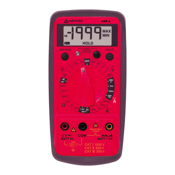
Amprobe 5XP-A Quick Manual
Resistance diagnostics for troubleshooting vibrating wire sensors and cables
Hide thumbs
Also See for 5XP-A:
- User manual (29 pages) ,
- User manual (84 pages) ,
- User manual (123 pages)

Related Manuals for Amprobe 5XP-A


Summary of Contents for Amprobe 5XP-A
-
Page 1: Quick Guide
V1.0 V1.0 QUICK GUIDE Resistance diagnostics for troubleshooting vibrating wire sensors and cables... - Page 2 V1.0 V1.0 INTRODUCTION Where damage to a sensor or cable is suspected this guide illustrates the way in which simple resistance checks can be taken to identify the possible cause of the problem. Resistance checks can be made with most types of multi-meter which are readily available in the market.
- Page 3 V1.0 V1.0 RESISTANCE OF THE THERMISTOR STEP 1 Set the range to 20kΩ or Ω if using a multi-meter which has automatic ranging. STEP 2 Connect the T+ (green) conductor to the red lead on the multi-meter and the T- (white) to the black lead on the multi-meter.
- Page 4 V1.0 V1.0 THERMISTOR LOOK UP TABLE Ohms Temp Ohms Temp Ohms Temp Ohms Temp Ohms Temp 201.1K 16.60K 2417 525.4 153.2 187.3K 15.72K 2317 507.8 149.0 174.5K 14.90K 2221 490.9 145.0 162.7K 14.12K 2130 474.7 141.1 151.7K 13.39K 2042 459.0 137.2 141.6K 12.70K...
- Page 5 V1.0 V1.0 RESISTANCE OF ALL INDIVIDUAL CONDUCTORS STEP 1 Set the range to 20kΩ or Ω if using a multi-meter which has automatic ranging. STEP 2 All pairs of conductors should be checked by connecting to the red and black leads on the multi- meter as follows:- Red &...
Need help?
Do you have a question about the 5XP-A and is the answer not in the manual?
Questions and answers