
Related Manuals for Allen-Bradley AADvance


Summary of Contents for Allen-Bradley AADvance
- Page 1 System Build Manual Original Instructions AADvance Controller Catalog Numbers T9110 T9300 T9310 T9401/2 T9431/2 T9451 T9481/2...
- Page 2 Important User Information Read this document and the documents listed in the additional resources section about installation, configuration, and operation of this equipment before you install, configure, operate, or maintain this product. Users are required to familiarize themselves with installation and wiring instructions in addition to requirements of all applicable codes, laws, and standards.
- Page 3 Labels may also be on or inside the equipment to provide specific precautions. SHOCK HAZARD: Labels may be on or inside the equipment, for example, a drive or motor, to alert people that dangerous voltage may be present. BURN HAZARD: Labels may be on or inside the equipment, for example, a drive or motor, to alert people that surfaces may reach dangerous temperatures.
- Page 4 Rockwell Automation Publication ICSTT-RM448J-EN-P - April 2018...
- Page 5 March 2015 Updates for Release 1.34. May 2015 Correct Documentation Feedback URL and Issue Record April 2018 Update for AADvance Release 1.40 Summary of changes in this Document Issue Topic Page Update hypertext link in Download section of Preface Update AADvance Release to 1.40...
- Page 6 Summary of Changes Rockwell Automation Publication ICSTT-RM448J-EN-P - April 2018...
- Page 7 The product compatibility and download center is www.rockwellautomation.com/rockwellautomation/support/pcdc.page? Select the Find Downloads option under Download In the Product Search field enter "AADvance" and the AADvance option is displayed. Double click on the AADvance option and the latest version is shown.
- Page 8 At the Search Knowledgebase tab select the option "By Product" then scroll down and select the ICS Triplex product AADvance. Some of the Answer ID’s in the Knowledge Base require a TechConnect Support Contract. For more information about TechConnect Support Contract Access Level and Features please click on the following link: https://rockwellautomation.custhelp.com/app/answers/detail/a_id/898272...
-
Page 9: Table Of Contents
Importing and Exporting Data......37 AADvance Workbench Licensing......37 Corrective Maintenance and Module Replacement . - Page 10 Before You Begin Required Tools Standard AADvance ......67 Specifying an Enclosure ........67 Maximum Enclosure Air temperature .
- Page 11 Table of Contents Connecting the AADvance Controller to the Network... 87 Chapter 5 Install the AADvance System Unpacking and Pre-assembly Checks ......89 Install Base Units and Termination Assemblies: Enclosure DIN Rail Assembly Method .
- Page 12 Additional Resources Associated AADvance Publications ......155 Regional Offices ......... . 156 Glossary .
-
Page 13: The Aadvance System
The flexibility of the design means that a system can meet a wide variety of business needs. An AADvance system is assembled to a scale and configuration that is applicable to your initial requirements and can be easily changed to meet your changing business requirements in the future. - Page 14 Chapter 1 The AADvance System Rockwell Automation Publication ICSTT-RM448J-EN-P - April 2018...
-
Page 15: The Aadvance Safety Controller
The system can also be used for safety implemented functions as well as applications that are not related to safety but are nevertheless critical to a business process. This AADvance controller offers the ability to make a cost- effective system to a customer's specification for any of the following applications: •... -
Page 16: Chapter 2
US MIL-1-46058C standard and meets IPC-CC-830. The coating is also UL approved. A Key benefit of the AADvance system is its flexibility. All of the configurations are readily achieved by combining modules and assemblies without using special cables or interface units. System architectures are user... - Page 17 PC workstations placed at convenient locations. The AADvance controller is developed and built for IEC 61131 compliance and includes support for all five programming languages. (Instruction List (IL) and Sequential Function Chart (SFC) languages are not supported by AADvance Workbench 2.x).
-
Page 18: Safety Features
• Easily transformed from a simplex non-safety system to a fault tolerant safety related system. • An AADvance platform provides a set of components that can be configured to meet a range of safety and fault tolerance user requirements within a single system such as - fault tolerant topologies 1oo1, 1oo2D and 2oo3. -
Page 19: Safety System Certification
Safety System Certification The AADvance Controller is certified by independent certifying bodies. Refer to the certificate for details of the standards included in the certification. Performance and Electrical... -
Page 20: Scan Times
1.761 ms Minimum cycle time overhead 39.3 ms Scan overhead for each module 0.04 ms The minimum overhead to the cycle time is a feature of the AADvance Workbench. The scan time is: Scan time = 39.3 ms + Sync time + Total number of modules * 0.04 ms... -
Page 21: System Installation Environment
The installation environment can be a source of common cause failure so it is necessary that the installation assessment covers the environmental Environment specification for the AADvance system and includes the following: • the prevailing climatic conditions • type of area, e.g. is it a hazardous or non-hazardous area •... -
Page 22: Environment Standards
The AADvance controller has been investigated and approved by UL for use as Industrial Control Equipment in hazardous locations, Class I, Division 2, Groups A, B, C and D in North America. - Page 23 The AADvance Safety Controller Chapter 2 • 9432 Analogue Input Module, 16 Channel • 9451 Digital Output Module • 9481 Analog Output Module • 9482 Analogue Output Module, 8 Channel. Listed Accessories for use with PLCs: • 9100 Processor Backplane •...
-
Page 24: Installation Requirements For Hazardous Environment
• Pollution Degree 4: Continuous conductivity occurs due to conductive dust, rain or other wet conditions. Installation Requirements The AADvance controller has been investigated and approved by UL for use as Industrial Control Equipment in hazardous locations, Class I, Division 2, for Hazardous Environment Groups A, B, C and D in North America. -
Page 25: File Number E251761
The AADvance Safety Controller Chapter 2 File Number E251761 The AADvance controller investigation and approval is contained in the following file certifications: • NRAG.E251761: Programmable Controllers for Use in Hazardous Locations Class I, Division 2, Groups A, B, C and D. -
Page 26: Environments
Chapter 2 The AADvance Safety Controller Certifications for Safety ATEX Certificate System Applications in Hazardous Environments TYPE EXAMINATION CERTIFICATE Equipment or Protective System intended for use in Potentially Explosive Atmospheres Directive 94/9/EC DEMKO 11 ATEX 1129711X Type Examination Certificate Number: Rev. - Page 27 The AADvance Safety Controller Chapter 2 Schedule [13] TYPE EXAMINATION CERTIFICATE No. [14] DEMKO 11 ATEX 1129711X Rev. 3 Report: 4786831849 [15] Description of Equipment: These devices are low-power, open-type programmable logic controllers that are intended for installation in an ultimate enclosure. The...
- Page 28 Chapter 2 The AADvance Safety Controller Schedule [13] TYPE EXAMINATION CERTIFICATE No. [14] DEMKO 11 ATEX 1129711X Rev. 3 Report: 4786831849 Voltage(Vdc) Current (mA) 9831 18-32 0-24 9832 18-32 0-24 9833 0-32 9851 18-32 9852 18-32 9892 18-32 9881 18-32...
-
Page 29: Iecex Ul Certificate
The AADvance Safety Controller Chapter 2 IECEx UL Certificate IECEx Certificate of Conformity INTERNATIONAL ELECTROTECHNICAL COMMISSION IEC Certification Scheme for Explosive Atmospheres for rules and details of the IECEx Scheme visit www.iecex.com Certificate No.: IECEx UL 12.0032X issue No.:2 Certificate history: Issue No. - Page 30 Chapter 2 The AADvance Safety Controller IECEx Certificate of Conformity Certificate No.: IECEx UL 12.0032X Date of Issue: 2014-05-28 Issue No.: 2 Page 2 of 4 Rockwell Automation Ltd. Manufacturer: Hall Road, Maldon CM9 4LA United Kingdom Additional Manufacturing location...
- Page 31 The AADvance Safety Controller Chapter 2 IECEx Certificate of Conformity Certificate No.: IECEx UL 12.0032X Date of Issue: 2014-05-28 Issue No.: 2 Page 3 of 4 Schedule EQUIPMENT: Equipment and systems covered by this certificate are as follows: These devices are low-power, open-type programmable logic controllers that are intended for installation in an ultimate enclosure.
- Page 32 Chapter 2 The AADvance Safety Controller IECEx Certificate of Conformity Certificate No.: IECEx UL 12.0032X Date of Issue: 2014-05-28 Issue No.: 2 Page 4 of 4 DETAILS OF CERTIFICATE CHANGES (for issues 1 and above): Issue 1: Addition of Model 9892 and updated drawings.
- Page 33 The AADvance Safety Controller Chapter 2 Annexe for IECEx UL 12.0032 Backplane Ratings Model Description Voltage Current (mA) Input/Output Ratings (Vdc) 9100 Processor Backplane 18-32 10.4A (400mA per slot) 9101 Dual Processor Backplane 18-32 10.4A (400mA per slot) 9300 I/O Backplane 18-32 9.6A...
-
Page 34: Module Label
Chapter 2 The AADvance Safety Controller Module Label The following label information must be attached to each module. KCC-EMC Registration Rockwell Automation Publication ICSTT-RM448J-EN-P - April 2018... -
Page 35: The Aadvance Workbench And Software Development Environment
The AADvance Safety Controller Chapter 2 The AADvance Workbench The AADvance software lets you design one complete control strategy, and then target parts of the strategy to individual controllers. Interaction between and Software Development the resources is automatic, significantly reducing the complexity of Environment configuration in a multi-resource system. -
Page 36: Operating Systems (32 Or 64 Bit)
Chapter 2 The AADvance Safety Controller Operating Systems (32 or 64 bit) The minimum workstation requirements for the application development software are as follows: • Microsoft Windows XP Service Pack 3 CAUTION: Do not use XP Professional x64 Edition. • Windows Vista •... -
Page 37: Importing And Exporting Data
• The demo license is a like a full license, but with a time limit. You can use all of the features of the AADvance Workbench for up to 30 days after first running the AADvance Workbench is first run. -
Page 38: Tuv Approved Operating System
TUV Approved Operating System The AADvance system runs an IEC 61508 approved operating system and the overall system is certified to IEC 61508, Part 1-7: 1998 - 2000 SIL 3. Main Components... - Page 39 The AADvance Safety Controller Chapter 2 Table 3 - Environmental Specification Attributes Value Operating Temperature Range: For use in Hazardous Environments: Processor Modules –25 °C to +60 °C (–13 °F to +140 °F) I/O Modules and Termination Assemblies –25 °C to +70 °C (–13 °F to +158 °F)
-
Page 40: Product Dimensions
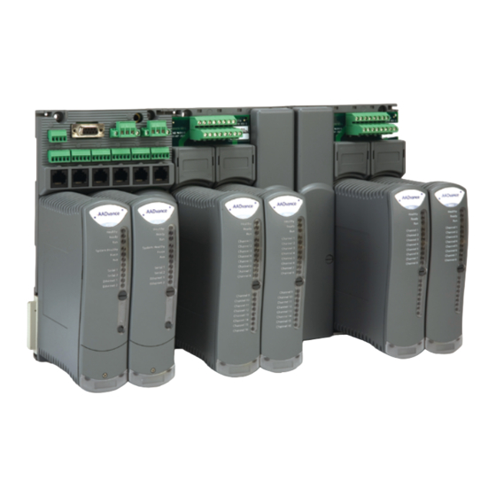
Chapter 2 The AADvance Safety Controller Product Dimensions A typical controller arrangement is shown with processor modules installed on the processor base unit and an I/O base unit mated with the processor base unit. I/O modules are installed on the base unit and a termination assembly plugged into the I/O base unit. - Page 41 The AADvance Safety Controller Chapter 2 Table 4 - Summary of Dimensions Attribute Value Base unit dimensions (H × W × D), approx. 233 mm × 126 mm × 18 mm (see text) (9-¼ in. × 5 in. × ¾ in.) Module dimensions (H ×...
-
Page 42: Compact Module Design
Figure 2 - An AADvance Module NOTE Standard AADvance modules have a plastic casing and are rated IP20: Protected against solid objects over 12 mm (1/2 in.) for example "fingers". There is no specific protection against liquids. -
Page 43: Module Polarization Keying
The AADvance Safety Controller Chapter 2 Module Polarization Keying For each I/O Module there is a matched termination assembly. The controller incorporates module polarization keying to make sure that they are correctly mated when installed. Sockets on the rear end plate align and mate with coding pins found on the termination assembly. -
Page 44: Module Locking Mechanism
Chapter 2 The AADvance Safety Controller Module Locking Mechanism Figure 4 - Locking Screw Each module carries a locking mechanism, which secures the module onto its base unit. The locking mechanism is in the form of a clamp screw, which can be seen on the front panel of the module and engaged by a quarter turn of a flat blade screwdriver. - Page 45 The AADvance Safety Controller Chapter 2 Figure 5 - Field Wiring Connections NOTE The recommended torque for termination assembly screw connectors is 5 Rockwell Automation Publication ICSTT-RM448J-EN-P - April 2018...
-
Page 46: Processor Base Unit
Chapter 2 The AADvance Safety Controller Processor Base Unit A processor base unit holds up to three processor modules: Rockwell Automation Publication ICSTT-RM448J-EN-P - April 2018... -
Page 47: External Ethernet, Serial Data And Power Connections
The AADvance Safety Controller Chapter 2 External Ethernet, Serial Data and Power Connections The processor base unit external connections are: • Earthing Stud • Ethernet Ports (E1-1 to E3-2) • Serial Ports (S1-1 to S3-2) • Redundant +24 Vdc powers supply (PWR-1 and PWR-2) •... -
Page 48: Processor Back-Up Battery
Chapter 2 The AADvance Safety Controller Processor Back-up Battery The 9110 processor module has a back-up battery that powers its internal Real Time Clock (RTC) and a part of the volatile memory (RAM). The battery only supplies power when the processor module is no longer powered from the system power supplies. - Page 49 The AADvance Safety Controller Chapter 2 Battery Location The battery is supplied separately and inserted into a slot behind a removable cover on the front panel of the processor module. The battery position is shown in the illustration: CAUTION: The battery may explode if mistreated. Do not recharge, disassemble or dispose of in a fire.
-
Page 50: Processor Maintenance Socket
Behind the removal cover on the processor front panel is a maintenance socket SK1. This socket is for maintenance use only. CAUTION: K1 is for maintenance only. When AADvance is installed in a hazardous location power must be disconnected or the area known to be free of ignitable concentrations of flammable gases or vapours when using this socket. -
Page 51: I/O Base Unit
The AADvance Safety Controller Chapter 2 I/O Base Unit An I/O base unit holds up to three I/O modules: Rockwell Automation Publication ICSTT-RM448J-EN-P - April 2018... -
Page 52: Termination Assemblies
The AADvance Safety Controller Termination Assemblies The AADvance system provides a range of termination assemblies to connect field wiring to the I/O modules. A termination assembly is a printed circuit equipped with screw terminal blocks for the field wiring (and in some cases fuses) and connectors for the plug-in I/O modules. - Page 53 The AADvance Safety Controller Chapter 2 Figure 8 - Top View Rockwell Automation Publication ICSTT-RM448J-EN-P - April 2018...
- Page 54 The T9892 Terminal Assembly module operates in conjunction with the T9451 Digital Output Module and provides 8 dual configuration output channels. It shares the same pin-out as the standard AADvance T9852 Digital Output Terminal Assembly and has the same coding peg configuration. The difference is that the T9892 has a separate connector for the field power input voltage connections (the left most terminal block shown below).
-
Page 55: Backplane Electrical Ratings
The AADvance Safety Controller Chapter 2 Backplane Electrical Ratings To comply with UL/CSA standards use the following voltage and current ratings for the Processor and I/O Backplanes when designing your power distribution: IMPORTANT These are the maximum allowed electrical ratings given by UL for the backplane load installed with the relevant TAs and modules. -
Page 56: Expansion Cable
Chapter 2 The AADvance Safety Controller Expansion Cable This is used to add extra rows of I/O base units and modules. Technical Features Controller Internal Bus Structure Internal communication between the processor modules and I/O modules is supported by command and response busses that are routed across the processor and I/O base units. -
Page 57: Internal Diagnostics And Fault Reset
I/O data and assists with fault containment. Internal Diagnostics and Fault Reset The AADvance controller contains comprehensive internal diagnostic systems to identify faults that occur during operation and trigger warnings and status indications. The diagnostic systems run automatically and test the system for faults related to the controller, and field faults related to field I/O circuits. -
Page 58: Remote Fault Reset
Workbench 2.x) for instructions on how to set up the variable. On-line updates I/O Configuration Changes The AADvance controller modular design makes it easy to create and change the I/O configuration. The on-line update facility enables you to make changes to the I/O configuration after the system is commissioned. -
Page 59: Hot Swap I/O For Business Critical Channels
IMPORTANT An on-line update could affect the operation of the controller such that the application is stopped or the I/O data flow is interrupted. The AADvance Safety Manual outlines the precautions you need to follow when doing on- line updates on a Safety System. -
Page 60: Ethernet Communication Protocols
NOTE When updating the firmware, it is recommended that RSWho is not actively browsing the 9110 Processor module. Ethernet Communication Protocols AADvance Ethernet ports are used to support several transport layer services; these services are listed in the following table: Protocol... - Page 61 The AADvance Safety Controller Chapter 2 Protocol Port Number Purpose 2222 CIP Produce & Consume I/O 5000 Trusted peer-to-peer 44818 CIP Produce & Consume Rockwell Automation Publication ICSTT-RM448J-EN-P - April 2018...
- Page 62 Chapter 2 The AADvance Safety Controller Rockwell Automation Publication ICSTT-RM448J-EN-P - April 2018...
-
Page 63: Application (Resource) Development
Chapter Application (Resource) Development The AADvance Workbench environment helps you with the task of automation during the life-cycle of your system, from system design to commissioning and the day to day operation and maintenance. For application (resource) development the AADvance Workbench has powerful, intuitive features and functionality to enhance simplicity. -
Page 64: Program Management Facilities
To show the links between the hardware-independent logical variables of the I/O Connection (Addressing AADvance application program and the physical I/O channel available on the of Physical I/O) controller, the AADvance Workbench has a powerful I/O connection editor. I/O channel links are easily identified between the logical programming and... -
Page 65: Off-Line Simulation And Testing
Application (Resource) The AADvance controller includes a Program Enable key that protects the application from access that has not been approved for change. The key must Program Security be fitted to the KEY connector on the T9100 processor base unit before you can download and make changes to an application (resource). - Page 66 Chapter 3 Application (Resource) Development Rockwell Automation Publication ICSTT-RM448J-EN-P - April 2018...
-
Page 67: Before You Begin
It covers preparatory information that you should read tasks you should complete for a successful installation. Required Tools Standard The installation and maintenance of the AADvance controller requires the following tools and test equipment: AADvance Standard Tools •... -
Page 68: Maximum Enclosure Air Temperature
être réduite. Enclosure Requirements for a Non-hazardous Environment ATTENTION: An AADvance system must be installed in an IP54 enclosure for use in a Pollution Degree 2 environment or similar in accordance with IEC 60664-1: 2007 ATTENTION: Un système AADvance doit être installé... -
Page 69: Enclosure Requirements For A Hazardous Environment - Class I, Division 2, Groups A, B, C And D
Before You Begin Chapter 4 Pollution Degree Definition For the purpose of evaluating creepage distances and clearances, the following four degrees of pollution in the micro-environment are established: • Pollution Degree 1: No pollution or only dry pollution occurs. The pollution has no influence. - Page 70 Chapter 4 Before You Begin AVERTISSEMENT: Conditions spéciales pour une utilisation sûre • Modèles 9110: la plage de température ambiante est de -25 °C à +60 °C; • Pour tous les autres modèles: la plage de température est de -25 °C à +70 °C;...
-
Page 71: Controller Mounting
être fourni pour couper l’alimentation en amont des fusibles avant leur remplacement. Controller Mounting An AADvance controller and I/O bases can be mounted using one of two methods: • A pair of parallel TS35 DIN rails. - Page 72 Chapter 4 Before You Begin Figure 10 - Free Space for Din Rails Fitting 233mm Each base unit (2 shown) occupies 126mm width. The flat panel drilling holes are shown in the illustration (Figure 11) below: Figure 11 - Flat Panel Mounting 126 mm 126 mm 19 mm...
-
Page 73: Base Units Rows And Expansion Cables
être réduite. Base Units Rows and Expansion Cables AADvance 9300 I/O base units connect to the right hand side of the 9100 processor base unit (I/O Bus 1) and to the right hand side of other 9300 I/O base units by a direct plug and socket connection. The I/O base units connect to the left hand side of the processor base unit by using the 93100 expansion cable (I/O Bus 2). - Page 74 Chapter 4 Before You Begin I/O base units. Base units are secured in place by top and bottom clips that are inserted into the slots on each base unit. Figure 12 - Connecting Base Units with Expansion Cables The expansion bus accessed from the right hand edge of the 9100 processor base unit is designated I/O Bus 1, while the bus accessed from the left hand edge is designated I/O Bus 2.
-
Page 75: Adding Field Cable Management
Before You Begin Chapter 4 individual module position within the controller can thus be uniquely identified by the combination of its bus and slot numbers, for example 1-01. The electrical characteristics of the I/O bus interface limit the maximum possible length of either of the two I/O buses (the combination of I/O base units and expansion cables) to 8 meters (26.24 ft.). -
Page 76: System Power Requirements
Chapter 4 Before You Begin System Power Requirements A controller's system power should be supplied from two different 24 Vdc (Nominal) power supplies with a common return path; that is, the 0 V return will be the same between the power feeds. Each controller also requires an external field power source for the field loops. -
Page 77: Controller Power Supply Requirements
A controller requires the following power supply sources: • A dual redundant power supply of + 24 Vdc with an operating range of 18 Vdc to 32 Vdc. The AADvance controller is designed to accept supply transient and interference according to IEC 61131 part 2. -
Page 78: Estimating Power Consumption
Chapter 4 Before You Begin Power Distribution Protection The power distribution circuit for each field input and for each output module must be protected, externally to the controller. Rockwell Automation recommend that power distribution must meet national and local panel wiring protection standards. -
Page 79: System Design Considerations For Heat Dissipation And Cooling
The heat in the enclosure is generated from several sources such as the power supplies, the AADvance modules and some of the field loop power. Use the following calculation and the data given in the tables to estimate the overall heat dissipation: •... -
Page 80: Estimate Aadvance Controller Weight
Maximum Channel Output Current OR Field Voltage/(2 x Load Resistance) Estimate AADvance Use the following table to make an estimate of the weight of your controller. Controller Weight Table 9 - AADvance Controller Module Weight Item Number Weight Allowance g... -
Page 81: Estimating Center Of Gravity Information
Estimating Center of Gravity If it is necessary to calculate the location of the center of gravity of an AADvance controller destined for a maritime or other shock-mounted Information application, it is reasonable to assume the center of gravity of each assembly of modules and their base unit is at the geometric center of the assembly. -
Page 82: Specifying The Workstation Pc
Chapter 4 Before You Begin Specifying the Workstation The minimum workstation requirements for the application development software are as follows: • Microsoft Windows XP Service Pack 3 CAUTION: Do not use XP Professional x64 Edition. • Windows Vista • Windows 7 •... -
Page 83: Design Considerations For Maintenance Activities
Before You Begin Chapter 4 Design Considerations for Maintenance Activities Maintenance Activities The design of the installation must allow preventive and corrective maintenance activities to take place. Corrective maintenance tasks will embrace the identification and renewal of defective modules and other assemblies and, when exhausted, renewal of the back-up battery within the T9110 processor module. -
Page 84: Design Provisions
Chapter 4 Before You Begin Design Provisions The design of the controller installation should make the following provisions: • Clear access to remove and install modules, termination assemblies, base units and security dongle (Program Enable key). Repair of controller modules will be by module replacement. A way for plant operations personnel to inspect the status LEDs on each module. -
Page 85: Rockwell Automation Publication Icstt-Rm448J-En-P - April
Before You Begin Chapter 4 Clear access to examine, remove and install fuses located on the termination assemblies. Rockwell Automation Publication ICSTT-RM448J-EN-P - April 2018... - Page 86 Chapter 4 Before You Begin Clear access to terminals and connectors for field, power and network wiring, and access to the wiring itself. Clear access to the Security Dongle (Program Enable Key) Rockwell Automation Publication ICSTT-RM448J-EN-P - April 2018...
-
Page 87: Connecting The Aadvance Controller To The Network
• A lock on the door of the enclosure, to deter unauthorized access and possible unofficial modifications. • Lighting. • Utility sockets. Connecting the AADvance The T9100 processor base unit has six auto-sensing 10/100BASE-TX Ethernet ports which allow it to connect to a local area network through Controller to the Network standard Rj45 Ethernet cable. - Page 88 Chapter 4 Before You Begin Refer to the illustration for an example. Rockwell Automation Publication ICSTT-RM448J-EN-P - April 2018...
-
Page 89: Install The Aadvance System
The system installation defines the steps that will ensure the system is correctly installed and ready for the on-site factory tests before the system is brought on- line. This chapter describes how to install the AADvance system hardware into the chosen enclosure. -
Page 90: Install Base Units And Termination Assemblies: Enclosure Din Rail
For a system build that uses DIN rails do the following: 1. Install the DIN rails. • The AADvance controller will be mounted onto one or more pairs of parallel DIN rails. For each pair of rails, mount the lower rail with its center line 101.0mm below the center line of the upper rail. - Page 91 Install the AADvance System Chapter 5 2. Mount the T9100 processor base unit • Place the T9100 processor base unit onto the DIN rails and position it towards the left, leaving space for the T9300 I/O base units to the right.
-
Page 92: Fitting Termination Assemblies
Chapter 5 Install the AADvance System Fitting Termination Assemblies Figure 16 - How to Fit Termination Assemblies 1. To fit termination assemblies do the following: • Insert the retaining clip on the back of the termination assembly into the slot on the I/O base unit. Press the termination assembly onto the base unit and then slide the assembly upwards as far as it will go. - Page 93 Install the AADvance System Chapter 5 2. Check coding pegs. • Observe the legend on the 9100 processor base unit (and repeated on some termination assemblies) which defines the six possible positions for a coding peg. The positions are numbered from 1 to 6.
-
Page 94: Allocations Of Coding Pegs
Chapter 5 Install the AADvance System Allocations of Coding Pegs Coding pegs are assigned to each module type as shown in the following table: Application Key A Key B Key C 9100 processor base unit (for 9110 processor module) 9801/2/3 digital input termination assemblies... -
Page 95: Connect The Ac Safety Ground Connection
Install the AADvance System Chapter 5 Connect the AC Safety The T9100 processor base unit has a ground stud which must be connected to the AC safety ground. Connect the ground stud to the AC safety ground Ground Connection bus-bar of the system or panel. - Page 96 Chapter 5 Install the AADvance System The processor base unit has a link between the +24 Vdc connections to the center terminal of each connector PWR-1 and PWR-2. This link may be useful to connect the +24 Vdc supply to further devices:...
-
Page 97: Procedure To Connect Serial Communications Cabling
Install the AADvance System Chapter 5 Procedure to Connect Serial The serial ports (S1-1 and S1-2; S2-1 and S2-2; S3-1 and S3-2) support the following signal modes depending on use: Communications Cabling • RS485fd: A four-wire full duplex connection that features different busses for transmit and receive. -
Page 98: Connecting Modbus Slave Devices To Serial Ports
Chapter 5 Install the AADvance System Terminal Function Description (4-wire) Function Description (2-wire) TRX_A Receive data A (inverting) Transmit/receive data A (inverting) TRX_B Receive data B (non-inverting) Transmit/receive data B (non-inverting) Instrument ground (signal ground) Instrument ground TX_B Transmit data B (non-inverting) -
Page 99: Connect A Slave Device, Full Duplex
Connect a Slave Device, Full Duplex You can use a full duplex serial connection to connect one MODBUS Slave device to the AADvance controller. To make the physical connection, do the following: 1. Select an applicable cable. We recommend 3-pair, overall shielded cable. -
Page 100: Connect Multiple Slave Devices, Full Duplex
Connect Multiple Slave Devices, Full Duplex You can use a full duplex serial connection to connect multiple MODBUS Slave devices to the AADvance controller. To make the physical connection, do the following: 1. Select an applicable cable. We recommend 3-pair, overall shielded cable. -
Page 101: Connect A Slave Device, Half Duplex
Connect a Slave Device, Half Duplex You can use a half duplex serial connection to connect a single MODBUS Slave device to the AADvance controller. To make the physical connection, do the following: 1. Select an applicable cable. We recommend 3-pair, overall shielded cable. -
Page 102: Connect Multiple Slave Devices, Half Duplex
Connect Multiple Slave Devices, Half Duplex You can use a half duplex serial connection to connect multiple MODBUS Slave devices to the AADvance controller. To make the physical connection, do the following: 1. Select an applicable cable. We recommend 3-pair, overall shielded cable. -
Page 103: System Security
As a minimum set up the following security measures: • AADvance must not be on a network with open unsecured access to the Internet. • The Firewall must be active on the Workstation, preventing access to the relevant Ethernet ports on each communication interface. -
Page 104: Digital Input Field Loop Circuits
Chapter 5 Install the AADvance System Digital Input Field Loop Circuits Recommended Field Loop Circuits This section contains recommended field loop circuits for line monitoring digital inputs used in Emergency Shutdown or Fire & Gas applications. Field Loop Circuit for Digital Input... - Page 105 Install the AADvance System Chapter 5 The suggested values for R1 and R2 are as follows: R1 = 15K 1%, 1W (maximum power dissipated is 47mW at 26.4V) R2 = 3K9 1%, 1W (maximum power dissipated is 182mW at 26.4V)
- Page 106 Chapter 5 Install the AADvance System Field Loop Circuit for Line Monitored Digital Input for Fire and Gas Systems (F & G) • The F&G circuit will also allow two devices to be in alarm without reporting short circuit. • All of the input circuits are suitable for simplex, dual and TMR configurations.
- Page 107 Install the AADvance System Chapter 5 Connections to 9801 Non-isolated Digital Input TA — 16 Channel Simplex • Apply a minimum tightening torque of 0.5 Nm (0.37 ft. lb.) to the terminal screws. Rockwell Automation Publication ICSTT-RM448J-EN-P - April 2018...
-
Page 108: Analogue Input Field Loop Circuits
Chapter 5 Install the AADvance System Connections to 9802/9803 Isolated Digital Input TA — 16 Channel Dual/TMR • Apply a minimum tightening torque of 0.5 Nm (0.37 ft. lb.) to the terminal screws. Analogue Input Field loop Circuits These circuits can be used for simplex, dual and triple configurations of analogue input modules. - Page 109 Install the AADvance System Chapter 5 Field Loop Circuit for 2-Wire Analogue Input Figure 17 - Wire Analogue Input Field Loop Rockwell Automation Publication ICSTT-RM448J-EN-P - April 2018...
- Page 110 Chapter 5 Install the AADvance System Field Loop Circuit for 3-Wire Analogue Input Figure 18 - Wire Analogue Input Field Loop Rockwell Automation Publication ICSTT-RM448J-EN-P - April 2018...
- Page 111 Install the AADvance System Chapter 5 Field Loop Circuit for 4-Wire Analogue Input Figure 19 - Wire Analogue Input Field Loop Analogue Input Slew Tolerance It is possible during sustained periods of abnormal input current slewing that channels can be declared faulted as a consequence of diagnostics otherwise designed to ensure the channels are operating within their designed safety accuracy.
- Page 112 Chapter 5 Install the AADvance System Connections to T9831 Non-isolated Analogue Input TA — 16 Channel Simplex • Apply a minimum tightening torque of 0.5 Nm (0.37 ft. lb.) to the terminal screws. Rockwell Automation Publication ICSTT-RM448J-EN-P - April 2018...
-
Page 113: Recommended Field Circuit For Digital Outputs
Install the AADvance System Chapter 5 Connections to T9832/T9833 Isolated Analogue Input TA — 16 Channel TMR • Apply a minimum tightening torque of 0.5 Nm (0.37 ft. lb.) to the terminal screws. Recommended Field Circuit for Digital Outputs This circuit is applicable for simplex and dual configurations of digital output modules. - Page 114 Chapter 5 Install the AADvance System Figure 20 - Digital Output Field Circuit WARNING: For inductive loads, a back EMF protection diode shall be fitted at the load. WARNING: A fuse rated minimum 32 Vdc, maximum 5 A for an input of 0 - 28.3 V and a maximum fuse current rating of 100 V for an input of 28.3 - 42.4...
- Page 115 Solutions Handbook. Accordingly it may be necessary to condition the field supply voltage or output signal such as by filtering or by appropriate choice of process safety time. For further information regarding how the AADvance digital output module detects field faults, see article 605753 on the Rockwell Knowledgebase website.
-
Page 116: Recommended Circuit For Analogue Outputs
Chapter 5 Install the AADvance System Figure 21 - Digital Output Termination Assembly Wiring • Apply a minimum tightening torque of 0.5 Nm (0.37 ft. lb.) to the terminal screws. Recommended Circuit for Analogue Outputs These circuits are suitable for simplex and dual configurations of analogue output modules. - Page 117 Install the AADvance System Chapter 5 System powered devices The above circuit is appropriate for devices that are powered by the system. The channel will pass a requested current between 0mA and 24mA. The field device could also be connected between the 24V supply and the Loop Plus terminal.
- Page 118 Chapter 5 Install the AADvance System Field powered devices The above circuit is appropriate for devices that are powered locally and expect a current-controlled signal loop. Ensure that the loop is wired to pass current to the Loop Plus terminal and return it on the Loop Minus terminal.
-
Page 119: Install Modules
Apply a minimum tightening torque of 0.5 Nm (0.37 ft. lb.) to the terminal screws. Install Modules The modules of the AADvance controller mount onto the base units. The processor module(s) mount onto the T9100 processor base unit, while the various I/O modules mount onto the T9300 I/O base unit and associated termination assemblies. -
Page 120: Install A 9110 Processor Module
Chapter 5 Install the AADvance System Install a 9110 Processor Do the following: • Before inserting a new processor module, examine it for damage. Module • The identification labels on the sides of the module will be hidden after the module is installed. Therefore before installation make a record of the location of the module and the details shown on the label. -
Page 121: Replace A Faulty Processor Back-Up Battery
Install the AADvance System Chapter 5 Replace a Faulty Processor Back-up Battery Use the following official Rockwell Automation battery or one of an equivalent specification. Part No and Description T9905: Polycarbon monofluoride Lithium Coin Battery, BR2032 (recommended type), 20 mm dia; Nominal voltage 3 V; Nominal capacity (mAh.) 190;... - Page 122 Chapter 5 Install the AADvance System Procedure To replace a faulty battery, do the following: 1. Use a small cross head screwdriver to release and remove the battery cover. 2. Remove the battery by pulling on the blue ribbon. Rockwell Automation Publication ICSTT-RM448J-EN-P - April 2018...
-
Page 123: Set The Real Time Clock Manually
SNTP it is recommended that you do so, as this will not only reset the processor clock but will also keep the time accurately during operation. Refer to the AADvance Configuration Guide for the SNTP set up instructions. The following applies: •... - Page 124 Chapter 5 Install the AADvance System • RTC Control: Year • RTC Control: Month • RTC Control: Day of Month • RTC Control: Hours • RTC Control: Minutes • RTC Control: Seconds • RTC Control: Milliseconds RTC Status Variables (All Word Inputs) •...
-
Page 125: Install I/O Modules
Install the AADvance System Chapter 5 Procedure to Set the Date and Time 1. Unlock the RTC Read variable so it turns FALSE. 2. Select each RTC Program Rack variable and enter the date and time values. 3. Toggle the RTC Write variable TRUE then FALSE to write the new date and time setting to the processor. - Page 126 Chapter 5 Install the AADvance System The ferrites supplied with the expansion cable are snap on components. Fit the ferrites 50 mm (2 in.) from each end and secure with cable ties either side of the ferrites. Connect Expansion Cable between T9100 Base Unit and T9300 I/O Base unit (I/O Bus2) 1.
- Page 127 Install the AADvance System Chapter 5 2. Insert the free end of the expansion cable into a right hand socket of a T9300 I/O base unit. • Insert a cable plug assembly into the right hand socket of the processor or I/O base unit.
-
Page 128: Fault Reporting Reference Information
Chapter 5 Install the AADvance System • Install the cable to the plug assembly and tighten the retaining screws by hand. 2. Connect the free end of the expansion cable to the left hand plug of an I/O base unit using a cable socket assembly. - Page 129 Install the AADvance System Chapter 5 Indicator Status Description No power or module is unlocked. GREEN Module is on-line and supplying data to/receiving data from application AMBER Module is inserted into a running system but not on-line. Push the Fault Reset button on any processor module to set the module to go on-line.
-
Page 130: Status Indicators On The 9110 Processor Module
Chapter 5 Install the AADvance System Status Indicators on the 9110 Processor Module Table 11 - Status Indicators on the T9110 Processor Module Indicator Status Description Healthy No power. • Flashes RED briefly after being installed as the module is booting up •... - Page 131 Install the AADvance System Chapter 5 Indicator Status Description Ready No power. • Module is booting up (10 to 20 seconds) or not educated or synchronized with partners. • Module is in the shutdown state. Flashing The module is being educated or synchronized.
- Page 132 Chapter 5 Install the AADvance System Rockwell Automation Publication ICSTT-RM448J-EN-P - April 2018...
-
Page 133: System Start-Up
When the checks and module installation and start up is completed successfully the system is ready for you to configure your system using the AADvance Workbench (see AADvance Configuration Guide for set up and configuration procedures) and then carry out Functional Acceptance Testing. -
Page 134: Procedure To Verify Build State
Chapter 6 System Start-Up Procedure to Verify Build Assess the build state of the system against the test documentation. Do the following: State • Compare the arrangement of the system with the General Arrangement drawings to make sure the system has been manufactured and assembled correctly. -
Page 135: Power Distribution And First Power Up
System Start-Up Chapter 6 4. Check that the circuit breakers and fuses of the correct capacity and rating are installed in the correct locations. 5. Check that all subsections are isolated from each other. Power Distribution and First Power Up NOTE Before you begin this task, you must have checked the power distribution integrity. -
Page 136: Start Up Process
System Configuration and Application Programming When the hardware is installed and running you need to set up the system configuration using the AADvance Workbench: • For Workbench 1.x refer to the AADvance Configuration Guide Doc ICSTT-RM405 for the detailed instructions on configuring a system. -
Page 137: Processor Module Start Up Process
System Start-Up Chapter 6 Processor Module Start Up Process NOTE When inserting more than one processor module they MUST be inserted one at a time and the module be allowed to educate (in the case of a 2nd and 3rd processor). - Page 138 Chapter 6 System Start-Up Procedure for Installation of a Second and Third Processor The second and third processor modules must have the same firmware version as the first processor. If the firmware revision is different upgrade the firmware using the ControlFLASH utility. IMPORTANT When inserting a second and third processor module they MUST be inserted one at a time and allowed to educate before inserting the next one.
-
Page 139: I/O Module Start-Up Process
System Start-Up Chapter 6 I/O Module Start-up Process The start-up sequence is different when a module is installed into an on-line system that is running compared to installing the module into a system that is off-line and has processor modules but no I/O modules installed. Table 14 - Single Module or First Module of a group Installation Procedure Step Task... -
Page 140: Processor Firmware Upgrades
Chapter 6 System Start-Up Step Task After approximately 3 seconds the module will now make the following status indications: Healthy GREEN Ready GREEN AMBER Channel 1 – 8 Push the Fault Reset button on the processor module and the Run indication goes GREEN. The module will now be on-line with the following status indications: Healthy GREEN... -
Page 141: Setting The Controller Ip Address For Aadvance Workbench
Controller IP Address The AADvance controller stores its IP address data in non-volatile memory in the 9100 processor base unit. The data is independent of the 9110 processor modules in the controller, and so the controller keeps the address information when you remove a processor module. -
Page 142: Configure The Controller Resource Number In The Controller
Configure the Controller When assembling a new AADvance controller (or install a new 9100 processor base unit) you have to configure the resource number stored in the controller. Resource Number in the... - Page 143 System Start-Up Chapter 6 The AADvance Discover utility scans the network for controllers and creates a list. 4. Locate the controller in the list and make sure that the status of the controller is Configurable. Rockwell Automation Publication ICSTT-RM448J-EN-P - April 2018...
- Page 144 Chapter 6 System Start-Up 5. Double-click the MAC address in the Controller ID field. • The resource and IP Address dialog box is displayed. 6. Enter the resource value into the Resource Number field, then click Apply. • Returning to the main window of the utility, the controller status will show Pending Restart.
-
Page 145: Configure The Ip Address In The Controller
System Start-Up Chapter 6 Configure the IP Address in When you assemble a new AADvance controller, or install a new 9100 processor base unit, you have to configure the IP Address stored in the the Controller controller. The procedure to configure the IP Address uses the AADvance Discover utility. - Page 146 Chapter 6 System Start-Up 5. Double-click on the MAC address in the Controller ID field. • The resource and IP address dialog box is displayed. 6. Enter the IP Address and Subnet Mask into the fields for each Ethernet port. 7.
-
Page 147: Devising Tests For Functional Acceptance
If a requirement cannot be physically demonstrated, devise a written analysis to show how the system achieves the requirement. The AADvance controller has been tested to the limits given in its module specifications. If appropriate, do the following: • Environmental tests, including electromagnetic compatibility, life- and stress-testing. - Page 148 Chapter 7 Functional Acceptance Testing Testing must be done on a known version of the controller. Record the type, serial number and physical location of each module so that the system can be dismantled, shipped and built with the modules in the same locations. Review and finalize the technical manuals which have been prepared for the maintenance and operation of the system.
-
Page 149: About Dismantling A System
Chapter Dismantling the AADvance System About Dismantling a System Dismantling Dismantling is the opposite of the system assembly procedure. Disposal It is necessary to make a plan for the collection, treatment, recovery and environmentally sound disposal of the equipment at the end of its life. Contact Rockwell Automation to discuss the applicable way to do this. - Page 150 Chapter 8 Dismantling the AADvance System Rockwell Automation Publication ICSTT-RM448J-EN-P - April 2018...
-
Page 151: Base Units
Chapter Parts List Base Units Part No. Part Description T9100 Processor base unit T9300 I/O base unit (3 way) Modules Part No. Part Description T9110 Processor module T9401 Digital input module, 24 Vdc, 8 channel, isolated T9402 Digital input module, 24 Vdc, 16 channel, isolated T9451 Digital output module, 24 Vdc, 8 channel, isolated, commoned T9431... -
Page 152: Termination Assemblies
Chapter 9 Parts List Termination Assemblies Part No. Part Description T9801 Digital input TA, 16 channel, simplex, commoned T9802 Digital input TA, 16 channel, dual T9803 Digital input TA, 16 channel, TMR T9831 Analogue input TA, 16 channel, simplex, commoned T9832 Analogue input TA, 16 channel, dual T9833... -
Page 153: Spares And Tools
Parts List Chapter 9 Spares and Tools Part No. Part Description T9901 Replacement input fuse 50 mA for T9801/2/3 and T9831/2/3, pack of 20 T9902 Replacement output fuse 10A for T9851/2, pack of 20 T9903 Replacement coding pegs (pack of 20) T9904 Replacement backplane clips (pack of 20) T9905... -
Page 154: Software
5 additional user licences, for use with T9084U T9087 IEC 61131 Workbench 2 T9030 OPC portal server T9033 AADvance DTM (for use with HART Pass-Through feature) Demonstration Unit Part No. Part Description T9141 AADvance Demonstration Unit (Including HMI) Miscellaneous Items Part No. -
Page 155: Associated Aadvance Publications
Chapter Additional Resources Associated AADvance For more information about the AADvance system refer to the related Rockwell Automation technical manuals shown in this document map. Publications Resource Document Number Safety Manual ICSTT - RM446 System Build Manual ICSTT - RM448... -
Page 156: Regional Offices
Solutions Handbook This technical manual describes the features, performance and functionality of the AADvance controller and systems. It gives guidance on how to design a system to satisfy your application requirements. System Build Manual This technical manual describes how to assemble a system, switch on and validate the operation of your system. -
Page 157: Glossary
Glossary Glossary of Terms accuracy The degree of conformity of a measure to a standard or a true value. See also 'resolution' . achievable safe state A safe state that is achievable. NOTE Sometimes, a safe state cannot be achieved. An example is a non- recoverable fault such as a voting element with a shorted switch and no means to bypass the effect of the short. -
Page 158: Rockwell Automation Publication Icstt-Rm448J-En-P - April
A plastic moulding to hide an unused slot in an AADvance base unit. boolean A type of variable that can accept only the values 'true' and 'false' . - Page 159 A grouping of all the application software and settings for a particular AADvance controller. The grouping must have a 'target' , but for an AADvance controller it can have only one 'resource' . consumer The consuming controller requests the tag from the producing controller.
- Page 160 Information calculated by the AADvance Workbench relating to the dictionary of variables and where those variables are used in a project. data access (DA) An OPC data type that provides real-time data from AADvance controllers to OPC clients.
- Page 161 Glossary fail operational state A state in which the fault has been masked. See 'fault tolerant' . fail safe The capability to go to a pre-determined safe state in the event of a specific malfunction. fault reset button The momentary action push switch located on the front panel of the 9110 processor module.
- Page 162 See live insertion. I/O base unit A backplane assembly which holds up to three I/O modules and their associated termination assembly or assemblies in an AADvance controller. Part number 9300. See 'I/O module' and 'termination assembly' . I/O module A collation of interfaces for field sensors (inputs) or final elements (outputs), arranged in a self-contained and standardized physical form factor.
- Page 163 A device which can change its state to give information. input (Workbench variable) In the context of an AADvance Workbench variable, this term describes a quantity passed to the Workbench from a controller.
- Page 164 AADvance Workbench. The settings include communication settings and messages. module locking screw The AADvance latch mechanism seen on the front panel of each module and operated by a broad, flat-blade screwdriver. Uses a cam action to lock to the processor base unit or I/O base unit.
- Page 165 Safety Instrumented Function continues to meet its designed performance criteria over the entire safety life cycle. protocol A set of rules that is used by devices (such as AADvance controllers, serial devices and engineering workstations) to communicate with each other. The rules encompass electrical parameters, data representation, signalling, authentication, and error detection.
- Page 166 RS-422 and RS-485 allow for higher transmission rates over increased distances. RTC Real-time clock. RTU Remote terminal unit. The MODBUS protocol supported by the AADvance controller for MODBUS communications over serial links, with the ability to multi-drop to multiple slave devices.
- Page 167 SIL rating. SNCP SNCP (Safety Network Control Protocol) is the Safety Protocol that allows elements of an AADvance System to exchange data. SNCP is a SIL 3 certified protocol which provides a safety layer for the Ethernet network making it a "Black Channel".
- Page 168 Glossary TMR Triple modular redundant. A fault tolerant arrangement in which three systems carry out a process and their result is processed by a voting system to produce a single output. TÜV certification Independent third party certification against a defined range of international standards including IEC 61508.
- Page 169 How Are We Doing? form at http://literature.rockwellautomation.com/idc/groups/literature/documents/du/ra-du002_-en-e.pdf. Rockwell Automation maintains current product environmental information on its website at http://www.rockwellautomation.com/rockwellautomation/about-us/sustainability-ethics/product-environmental-compliance.page. Allen-Bradley, Rockwell Software, and Rockwell Automation are trademarks of Rockwell Automation, Inc. Trademarks not belonging to Rockwell Automation are property of their respective companies.
Need help?
Do you have a question about the AADvance and is the answer not in the manual?
Questions and answers