Table of Contents
Advertisement
Quick Links
Advertisement
Table of Contents

Related Manuals for Baldor BC140


Summary of Contents for Baldor BC140
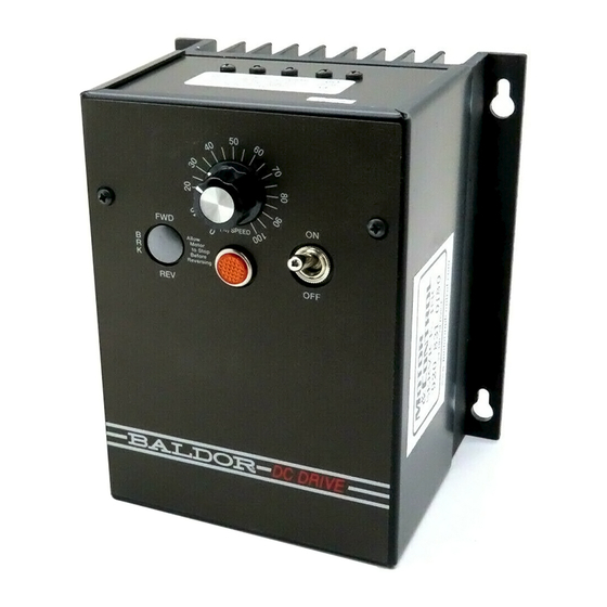
- Page 1 BC140 / BC140-FBR DC CONTROL Installation & Operating Manual 6/15 MN703...
- Page 2 Any trademarks used in this manual are the property of their respective owners. Important: Be sure to check www.baldor.com to download the latest version of this manual in Adobe Acrobat PDF format.
-
Page 3: Table Of Contents
Table of Contents Chapter 1 Introduction Introduction ..............1-1 Safety Notice . - Page 4 MN703...
-
Page 5: Introduction
Plug-in Horsepower Resistor®. The standard model, BC140, controls all motors through 3/4 HP at 115 Volt AC line input and 1-1/2 HP at 230 Volt AC line input. By installing the Auxiliary Heat Sink (see Table 1-2), the horsepower range is increased to 1 HP at 115 Volt AC line input and 2 HP at 230 Volt AC line input. -
Page 6: Receiving
Do not connect AC power to the Motor terminals A1 and A2. Connecting AC power to these terminals may damage the control. Caution: Baldor recommends not to use Grounded Leg Delta transformer power leads that may create ground loops. Instead, we recommend using a four wire Wye. Caution: Suitable for use on a circuit capable of delivering not more than 5,000 RMS symmetrical short circuit amperes listed here at rated voltage. -
Page 7: Installation
Chapter 2 Installation WARNING: Do not use this drive in an explosive environment. An explosion can cause serious or fatal injury. This drive is not explosion proof. Introduction The control is designed with a NEMA-1 / IP-40 enclosure for indoor use. It is recommended that the control be mounted vertically on a flat surface with adequate ventilation. -
Page 8: Electrical Connections
Electrical Connections Connection terminals are shown in Figure 2-2. Figure 2-2 AC Line, Armature, Field*, and Ground Connections Barrier Terminal Block Field Armature 115 or 208/230 Volts Ground (Earth) AC Line Input DC Motor Ground (Earth) AC Power Verify AC Line voltage matches to control voltage rating, (115/208/230VAC - 50/60 Hz. 1phase). Connect AC Line to L1 and L2 terminals and tighten to correct torque (Table 2-1). -
Page 9: Plug-In Horsepower Resistor
Table 2-2 Armature and AC Line Fuse Chart Motor Horsepower Approximate Motor Fuse Selection Current (Amps DC) (AC Amps) 90VDC 180VDC Armature Line 1/100 1/50 1/50 1/25 1/30 1/15 0.33 1/20 1/10 0.75 1/15 1/12 0.85 1.25 1½ *With optional Auxiliary Heat Sink (Catalog No. BC143). Table 2-3 Field Connection (Shunt Wound Motors Only) AC Input Voltage Voltage Selector... -
Page 10: Important Considerations
Important Considerations Motor Type The BC140 / BC140-FBR is designed for permanent magnet (PM) and Shunt Wound DC motors. Controls operated on 115 Volt AC line input are designed for 90 Volt SCR rated motors. Controls operated on 230 Volt AC line input are designed for 180 and 90 Volt (step-down) SCR rated motors. -
Page 11: Startup & Adjustments
Startup & Adjustments The Voltage Select Switch is located under the cover and must be set before applying power to the control. Figure 2-4. For 208/230 Volt AC Line Input Set the Voltage Select Switch to the 230 position (factory setting). The switch toggle should be in the lower position with 230 displayed at the top. - Page 12 For moderate changes in the maximum speed, there will be a slight effect on the minimum speed setting when the minimum is set to zero. There may be significant variation in the minimum speed setting if the minimum speed is at a higher than zero setting. Acceleration Trimpot (ACCEL) The ACCEL Trimpot is provided to allow for a smooth start over an adjustable time period each time the AC power is applied or the Main Speed Potentiometer is adjusted to a higher speed.
-
Page 13: Operation
Troubleshooting The BC140 / BC140-FBR has LEDs to display the control’s operational status. Power On (PWR ON) LED and Pilot Light When the AC power is applied to the control and the On/Off AC Line Switch is set ON, the PWR ON LED, on the PC board, will illuminate green and the Pilot Light, on the front cover, will illuminate orange. - Page 14 Table 2-4 Troubleshooting Guide (without Optional Forward-Brake-Reverse Switch) Symptom Possible Cause Suggested Corrective Action Faulty connections or loose Check and correct connections. connections. No braking action in brake mode. Defective Brake Resistor. Replace Forward-Brake-Reverse Switch assembly. Overload condition. Remove overload. Incorrect Plug-In Horsepower Install the correct Plug-In Horsepower Resistor®.
-
Page 15: Optional Auxiliary Heat Sink (Catalog No. Bc143
Figure A-2 shows the connections of the Forward-Brake-Reverse Switch to the speed control and the Barrier Terminal Block. * BC144 is factory installed on BC140-FBR model. Figure A-2 Optional Forward-Brake- Reverse Switch Connections MN703... - Page 16 Optional RFI Filter (BC24-LF) Panel mount. Rated 24 Amps at 115 and 208/230 Volts AC, single phase. Complies with CE Directive 89/336/EEC (EN55022 and/or EN55011) relating to the EMC Class A Industrial Standard. MN703...
- Page 19 Baldor District Offices UNITED STATES ILLINOIS NEW YORK TENNESSEE AUBURN MEMPHIS CHICAGO ARIZONA ONE ELLIS DRIVE 4000 WINCHESTER ROAD 340 REMINGTON BLVD. PHOENIX AUBURN, NY 13021 MEMPHIS, TN 38118 BOLINGBROOK, IL 60440 PHONE: 315-255-3403 4211 S 43RD PLACE PHONE: 630-296-1400...
- Page 20 MN703-0615 Baldor Electric Company P.O. Box 2400, Fort Smith, AR 72902-2400 U.S.A., Ph: (1) 479.646.4711, Fax (1) 479.648.5792, International Fax (1) 479.648.5895 www.baldor.com © Baldor Electric Company All Rights Reserved. Printed in USA. MN703 (A40244B) - Rev E 6/15...