Table of Contents
Advertisement
INSTRUCTION 24-9223
MODEL 300
COMBUSTION ANALYZER
(Standard Efficiency Equations,
Siegert Efficiency Equations,
and NSX Version)
Operation/Maintenance
Rev. 2 – November 1999
Bacharach, Inc.
625 Alpha Drive, Pittsburgh, PA 15238
Phone: 412-963-2000 • FAX: 412-963-2091 • Web: www.bacharach-inc.com
.
® Registered Trademark
Printed in U.S.A
Advertisement
Table of Contents

Related Manuals for Bacharach 300


Summary of Contents for Bacharach 300
- Page 1 MODEL 300 COMBUSTION ANALYZER (Standard Efficiency Equations, Siegert Efficiency Equations, and NSX Version) Operation/Maintenance Rev. 2 – November 1999 Bacharach, Inc. 625 Alpha Drive, Pittsburgh, PA 15238 Phone: 412-963-2000 • FAX: 412-963-2091 • Web: www.bacharach-inc.com ® Registered Trademark Printed in U.S.A...
- Page 2 Seller at the factory of manufacture and shown to Bacharach Inc.’s reasonable satisfaction to have been defective; provided that written notice of the defect shall have been given by Buyer to Bacharach Inc. within one (1) year after the date of delivery of this Product by Bacharach, Inc.
- Page 3 MODEL 300 COMBUSTION ANALYZER WARNINGS! • Burn hazard. DO NOT touch the Model 300 Combustion Analyzer probe after it is removed from a stack. Allow the probe to cool before han- dling. • Burn hazard. When emptying filter/trap bowl and particulate trap, be aware that both traps may contain hot and mildly corrosive water.
-
Page 4: Table Of Contents
MODEL 300 COMBUSTION ANALYZER TABLE OF CONTENTS 1 INTRODUCTION ................1-1 1.1 Scope of Manual ................1-1 1.2 Basic Features ................1-2 1.3 Optional Features ............... 1-3 1.4 Basic Panel Functions & Displays ..........1-4 1.4.1 CAL, FUEL, and RUN Keys ..........1-4 1.4.2... - Page 5 MODEL 300 COMBUSTION ANALYZER TABLE OF CONTENTS (Cont.) 4 CALIBRATION ..................4-1 4.1 Sensor and/or Control Panel Removal ........4-3 4.2 Ambient Temperature Calibration - R24 ........4-5 4.3 Toxic Gas Span Calibration ............4-7 4.3.1 CO Span Calibration - R9 ..........4-7 4.3.2 Optional NOX &...
- Page 6 BATTERY PACK SPECIFICATIONS (A battery-powered unit may be run off the charger, if required.) Output Voltage: ....5 VDC Charging Input Voltage: ..8 VDC from Bacharach Charger (Refer to Section 6 for part numbers) Charging Time: ....5-6 hours Operating Time ....
- Page 7 MODEL 300 COMBUSTION ANALYZER ACCURACY (68°F [20°C], 45% RELATIVE HUMIDITY) Stack Temperature ..±1% full scale Oxygen ......±0.6% O Carbon Monoxide ... ±5% reading or ±10 ppm, whichever is greater (Optional) ....±5% reading or ±10 ppm, whichever is greater (Optional) ....
- Page 8 MODEL 300 COMBUSTION ANALYZER FUNCTIONS (Cont.) Computes and Displays: • Combustion Efficiency (1 to 99.9%) • Stack Loss (1 to 99.9%) • Carbon Dioxide Level (1 to 20%) • Excess Air (1 to 250%) Additionally Displays: • Fuel selected: Standard Efficiency Equations...
- Page 9 MODEL 300 COMBUSTION ANALYZER FUNCTIONS (Cont.) Additionally Displays (Cont.): • Analyzer errors or warnings Main Display - No errors or warnings to report. W*CO - CO channel warning. E*O2 - Oxygen channel error. E*TC - Thermocouple channel error. E*AM - Ambient temperature channel error.
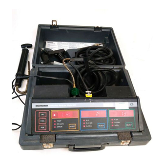
- Page 10 MODEL 300 COMBUSTION ANALYZER Figure A. Model 300 Combustion Analyzer (Typical Configuration) viii Instruction 24-9223...
-
Page 11: Introduction
MODEL 300 COMBUSTION ANALYZER INTRODUCTION The Model 300 Combustion Analyzer is an efficiency analyzer designed for medium to large, condensing and non-condensing, industrial burners. A microprocessor controls the analyzer’s operation along with calculating burner efficiency. SCOPE OF MANUAL The following information is provided in this manual: 1. -
Page 12: Basic Features
• Stack Temperature (°F /°C) • % Excess Air • % CO Because the Model 300 Combustion Analyzer is a “smart” instrument, its operation is fast and virtually mistake-proof. Programmed routines lead the operator through the proper sequence of start-up and test procedures, signaling what action is required, and locking the instrument into a waiting mode until the proper action is taken. -
Page 13: Optional Features
MODEL 300 COMBUSTION ANALYZER OPTIONAL FEATURES • Printer, prints out a copy of the efficiency test results. The NSX version of the Model 300 Combustion Analyzer adds the follow- ing features (For information on upgrading to NO and/or SO , contact your distributor or the factory): •... -
Page 14: Basic Panel Functions & Displays
MODEL 300 COMBUSTION ANALYZER BASIC PANEL FUNCTIONS & DISPLAYS 1.4.1 CAL, FUEL, and RUN Keys Press to start 60 second calibration cycle. When left display shows CAL, the CAL key must be pressed before the analyzer can continue its operation. -
Page 15: Left Display And Select Key
MODEL 300 COMBUSTION ANALYZER 1.4.2 Left Display and Select Key Figure 1-1. Left Display Press to show TEMP, CO (ppm), or ERROR information on the four-segment alphanumeric display. Also press with the FUEL key held down to change fuels after performing an efficiency test. - Page 16 MODEL 300 COMBUSTION ANALYZER Display Mode Indicator Lit Meaning of Display Indication Stack temperature detected by probe (°F or °C, see label inside case). Carbon Monoxide concentration as measured by the CO sensor. OK – No errors or warnings to report.
-
Page 17: Middle Display And Select Key
MODEL 300 COMBUSTION ANALYZER 1.4.3 Middle Display and Select Key Figure 1-3. Middle Display Press to show %O , % EX AIR, or O CELL information on the three-segment numeric display. The Display Mode Indicators identify what is being shown on the display. -
Page 18: Right Display And Select Key
MODEL 300 COMBUSTION ANALYZER 1.4.4 Right Display and Select Key Figure 1-4. Right Display Press to show %EFF, %LOSS, or %CO information on the three-segment numeric display. The Display Mode Indicators identify what is being shown on the display. Display Mode... -
Page 19: Optional Auxiliary Panel Functions & Displays
MODEL 300 COMBUSTION ANALYZER OPTIONAL AUXILIARY PANEL FUNCTIONS & DISPLAYS Functions of the three display windows on the auxiliary display panel are described in Sections 1.5.1 thru 1.5.3 below. NOTE: With or without an NO (middle display) and/or SO (right display) sensor installed, each display shows warning, failure, and error messages (refer to Section 3.5) that pertain to... - Page 20 MODEL 300 COMBUSTION ANALYZER NOTES 1-10 Instruction 24-9223...
-
Page 21: Set-Up
SET-UP The charts and procedures in this section describe how to set-up the Model 300 for combustion efficiency testing. If any difficulty is encoun- tered while performing these procedures, please refer to Section 4 and/or 5 for assistance in resolving the problem. -
Page 22: 230 Vac Plug Installation
MODEL 300 COMBUSTION ANALYZER 230 VAC PLUG INSTALLATION Due to the many different AC receptacles available for 230 VAC, a wall plug is not supplied on the instrument’s 230 VAC power supply. An IEC receptacle is provided for the input. An IEC 380 cord set must be ob- tained, with the proper type of AC wall outlet, for the country where the instrument is to be used. -
Page 23: Probe Connection
MODEL 300 COMBUSTION ANALYZER PROBE CONNECTION See Fig. 2-2. To connect the probe, simply attach its air tubing to the filter/trap, and plug its thermocouple connector into the receptacle at the rear of analyzer’s control panel, noting the polarity of the connector. -
Page 24: Initial Start-Up And Adjustment
MODEL 300 COMBUSTION ANALYZER INITIAL START-UP AND ADJUSTMENT Flow Chart #2 INITIAL START-UP Section 2.5 & 4.3 At the End of the 60 Turn ON Unit Second CAL Cycle Section 2.5, Step 1 Section 2.5, Step 5 Left Display - (FUEL) After 5 Seconds Mid. - Page 25 MODEL 300 COMBUSTION ANALYZER Before using your Model 300 Combustion Analyzer in an actual efficiency test, verify that the analyzer indicates 20.9% oxygen in fresh air, and correctly measures ambient air temperature. 1. Turn on the analyzer by either plugging it in, or by setting its battery pack switch (see Fig.
- Page 26 MODEL 300 COMBUSTION ANALYZER 5. At the end of the calibration cycle, the left display should show FUEL, with the middle and right displays blank, the Optional clock will show the time, and Optional auxiliary panel middle and right displays will read 0 ppm.
-
Page 27: Sensor Checks
MODEL 300 COMBUSTION ANALYZER SENSOR CHECKS Flow Chart #3 SENSOR CHECKS Section 2.6 & 4.3 Sensor Check Qualified Test Section 2.6 Personnel Span Calibration Section 4.3 Send to Bacharach Service Center R9-CO Span Section 4.3.1 Optional NO & SO Span Calibration Section 4.3.2... -
Page 28: Optional Clock Setting
Should you have reason to suspect the accuracy of either sensor, BACHARACH recommends that the unit be sent to a qualified Service Center (see the inside back cover) for calibration. - Page 29 MODEL 300 COMBUSTION ANALYZER 3. See Fig. 2.5. Using the end of a straightened paper clip, or similar object, press the clock’s MODE switch to cycle through the clock-mode settings. The following example shows what will be shown in the clock display after each depression of the MODE switch for: Sunday, the 9th of April, 1995, 3:58 PM.
-
Page 30: Optional Analyzer Configuration
Figure 2-5. Clock Display Switches OPTIONAL ANALYZER CONFIGURATION Analyzer configuration is determined by ten internal switches, which should have been preset by the Bacharach Sales Center per the sales agreement. If, however, a switch setting needs to be changed, refer to Section 5.8. -
Page 31: Operation
MODEL 300 COMBUSTION ANALYZER OPERATION This sections describes: • Performing an Efficiency Test • Gas Sample Points • Installing the Probe • Printer Operation • Error, Warning and Failure Displays • Recalibration after an Efficiency Test • Changing Fuels • Combustion Analyzer Shutdown & Storage •... - Page 32 MODEL 300 COMBUSTION ANALYZER Flow Chart #5 EFFICIENCY TEST Section 3 Turn ON Analyzer Press FUEL key to proper fuel Step 1 Insert Probe in Stack Sample Hole See Sections 3.2 & 3.3 Step 6 Wait for Unit to go...
-
Page 33: Performing An Efficiency Test
MODEL 300 COMBUSTION ANALYZER PERFORMING AN EFFICIENCY TEST This procedure describes how to initially calibrate the Model 300 Com- bustion Analyzer and perform a combustion efficiency test. Each time the combustion analyzer is turned on, its microprocessor begins its initial start-up routine. This routine directs the operator to calibrate the analyzer and select the proper fuel. - Page 34 MODEL 300 COMBUSTION ANALYZER 4. Press CAL key to start calibration cycle. The following should be seen: • Left display show CAL. • Middle display show millivolt output of O cell. Should the cell’s output fall outside acceptable limits, an E*O2 error will occur (Refer to Section 3.5).
- Page 35 MODEL 300 COMBUSTION ANALYZER • Optional NOx and/or SO concentrations are displayed on the auxiliary panel. • Optional clock displays the current time. NOTE: It’s normal for the Display Mode Indicators to occasion- ally blink due to the complexity of the efficiency calculations.
-
Page 36: Gas Sampling Points
MODEL 300 COMBUSTION ANALYZER GAS SAMPLING POINTS The Model 300 Combustion Analyzer requires a " (9.5 mm) minimum diameter sampling hole to accommodate the analyzer’s probe-stop. Locate the sampling point downstream from the last heat exchanger, and upstream from any source of dilution. -
Page 37: Printer Operation
MODEL 300 COMBUSTION ANALYZER Figure 3-3. Installing the Probe PRINTER OPERATION Press the PRINT switch (Fig. 3-4) to obtain a hard copy of the efficiency test results either during an efficiency test, or after its completion – the printer will not operate at any other time. Observe that the PRINT LED will glow as the printer operates. - Page 38 MODEL 300 COMBUSTION ANALYZER Figure 3-4. Printer Controls BACHARACH MODEL CA3ØØNSX * * * * * * * * * * * * COMBUSTION ANALYZER BACHARACH MODEL 3ØØ ________________ * * * * * * * * * * * * SER.
-
Page 39: Error, Warning And Overrange Displays
MODEL 300 COMBUSTION ANALYZER ERROR, WARNING AND OVERRANGE DISPLAYS 3.5.1 Basic Error, Warning and Overrange Displays Three levels of problems are detected by the analyer’s microprocessor, and then identified on the left display in the form of E* (error), W* (warning) and OR (overrange) messages. -
Page 40: Optional Error, Warning, And Overrange Displays
MODEL 300 COMBUSTION ANALYZER 2. If a recalibration cycle is started, allow the cycle to finish before proceeding. If RUN is displayed, press the RUN key to restart the efficiency test. If FUEL is displayed, press the FUEL key until the desired fuel is shown in the left display. - Page 41 MODEL 300 COMBUSTION ANALYZER TABLE 3-1. Basic Error, Warning and Overrange Displays Display Shows Display Meaning Remedy ----- No errors, warnings or overranges to report. Remove and then reapply power to W*CO Warning, CO level over the analyzer. Allow pump to run...
- Page 42 MODEL 300 COMBUSTION ANALYZER TABLE 3-1. Basic Error, Warning and Overrange Displays (Cont.) Display Shows Display Meaning Remedy E*TC Error, thermocouple Allow thermocouple to stabilize at temperature below – room temperature and then recali- 100° or above 2300° F brate the analyzer.
- Page 43 MODEL 300 COMBUSTION ANALYZER TABLE 3-2. Optional Error, Warning and Overrange Displays Left Middle Right Display Display Display Meaning of Display BATT Warning – sensor bias battery voltage getting low. This message is displayed at the conclu- sion of the calibration cycle, and once every 10 seconds during an efficiency test.
-
Page 44: Recalibration After An Efficiency Test
MODEL 300 COMBUSTION ANALYZER RECALIBRATION AFTER AN EFFICIENCY TEST If you are unsure about the calibration of the analyzer after performing an efficiency test, it can be recalibrated as follows: NOTE: Recalibration is essentially the same as the initial power-up calibration cycle, with the exception that the recalibration cycle can be aborted at any time by pressing the CAL key. -
Page 45: Changing Fuels
COMBUSTION ANALYZER SHUTDOWN AND STORAGE Proceed as follows to shut down and store your Model 300 Combustion Analyzer: 1. If not already stopped, press RUN key to stop the analyzer’s pump. - Page 46 MODEL 300 COMBUSTION ANALYZER WARNING! Both traps may contain hot and mildly acidic water. Take the necessary precautions to avoid being burned. CAUTION: When emptying traps, be careful not to spill water into the combustion analyzer case. a. See Fig. 3-1. Remove filter/trap from control panel; then unscrew and empty its bowl.
- Page 47 To avoid crimping the hose when the case is closed, loop hose under strap per Fig. 3-7. 8. Flip down optional display. CAUTION: DO NOT store the Model 300 Combustion Analyzer at tempera- tures below – 4°F (– 20°C). Figure 3-7. Storage of Combustion Analyzer Components Instruction 24-9223...
-
Page 48: Charging The Battery Pack
MODEL 300 COMBUSTION ANALYZER CHARGING THE BATTERY PACK If the analyzer is powered by a battery pack, charge the pack as described below (also see Fig. 3-8). A fully charged battery pack will run the analyzer through at least 200 combustion efficiency tests (6 hours minimum);... -
Page 49: Calibration
MODEL 300 COMBUSTION ANALYZER CALIBRATION NOTE: Analyzer calibration is available from authorized Bacharach Service Centers. This section describes how to check the combustion analyzer’s calibration, and how to adjust the three potentiometers. • Sensor and/or Control Panel Removal • Ambient Temperature Adjust •... - Page 50 MODEL 300 COMBUSTION ANALYZER Figure 4-1. Removing Sensor Cover Figure 4-2. Printer Screw Location Instruction 24-9223...
-
Page 51: Sensor And/Or Control Panel Removal
MODEL 300 COMBUSTION ANALYZER SENSOR AND/OR CONTROL PANEL REMOVAL To adjust potentiometers R9, R19, R24, POT1 & POT2, or to replace the sensors, the sensor and/or control panels must first be removed from the case as follows: Equipment Needed • Medium Flat-Blade Screwdriver Procedure 1. - Page 52 MODEL 300 COMBUSTION ANALYZER Figure 4-3. Screw Locations Figure 4-4. Accessing Control Panel Potentiometer (Typical Configuration) Instruction 24-9223...
-
Page 53: Ambient Temperature Calibration - R24
MODEL 300 COMBUSTION ANALYZER AMBIENT TEMPERATURE CALIBRATION - R24 This procedure calibrates the combustion analyzer’s ambient temperature transducer (component D7, mounted on the printed circuit board) to room temperature, using the R24 potentioneter (see Fig. 4-6). Equipment Needed (See Section 6 for Part Numbers) •... - Page 54 MODEL 300 COMBUSTION ANALYZER 4. Power up the analyzer as follows: a. Turn on the analyzer by either plugging it in, or by setting its battery pack switch to ON. b. Press CAL key to start the 60 second calibration cycle.
-
Page 55: Toxic Gas Span Calibration
MODEL 300 COMBUSTION ANALYZER TOXIC GAS SPAN CALIBRATION The following procedure calibrates the combustion analyzer’s sensors to a known concentration of gas. 4.3.1 CO Span Calibration - R9 Equipment Needed (See Section 6 for Part Numbers) • Calibration Kit • Carbon Monoxide Gas Cylinder, •... - Page 56 MODEL 300 COMBUSTION ANALYZER Figure 4-7. CO Sensor Calibration Setup 5. Press the left SELECT key until the CO (ppm) indicator is lit. 6. Connect calibration setup to the instrument. Then adjust regulator on gas cylinder for a flowmeter indication of 0.5 to 1 SCFH.
-
Page 57: Thermocouple Span Calibration - R19
Should you have reason to suspect the accuracy of either sensor, BACHARACH recommends that the unit be sent to a qualified Service Center (see the inside back cover) for calibration. If you have the qualified... - Page 58 MODEL 300 COMBUSTION ANALYZER Equipment Needed (See Section 6 for Part Numbers) • Thermometer, precision grade, 0° to 220°F (–20° to 150°C) • Boiling Water Bath • Potentiometer Adjustment Tool Procedure 1. Remove filter/trap. Important: This step prevents boiling water from being sucked up through the probe.
-
Page 59: High-Range Thermocouple Calibration
MODEL 300 COMBUSTION ANALYZER 9. Replace filter/trap; then if no other calibration adjustments are to be made, replace control panel and printer (if applicable). Figure 4-8. Low-Temperature Range Thermocouple Calibration Setup 4.4.2 High-Range Thermocouple Calibration Up to 2000°F (1093°C) This procedure calibrates the probe’s thermocouple to be accurate up to a temperature of 2000°F (1093°C). - Page 60 MODEL 300 COMBUSTION ANALYZER Procedure 1. Remove filter/trap and thermocouple plug from control panel. 2. Remove control panel per Section 4.1. 3. Power up the analyzer as follows: a. Turn on the analyzer by either plugging it in, or by setting its battery pack switch to ON.
- Page 61 MODEL 300 COMBUSTION ANALYZER Figure 4-9. High-Temperature Range Thermocouple Calibration Setup TABLE 4-1. MV LEVEL VS. AMBIENT TEMPERATURE FOR THERMOCOUPLE CALIBRATION @ 1700°F (927°C) Ambient Temp °F (°C) Applied 60 (16) 37.8 70 (21) 37.5 80 (27) 37.3 90 (32) 37.1...
-
Page 62: Oxygen Sensor Calibration
MODEL 300 COMBUSTION ANALYZER OXYGEN SENSOR CALIBRATION The oxygen sensor does not require manual calibration. Automatic calibration to an oxygen level of 20.9% occurs each time the combustion analyzer runs through its calibration cycle – the microprocessor assumes fresh air is being sampled during calibration. -
Page 63: Maintenance
Bacharach Service Center. Any maintenance performed by an unauthorized service organization will void the instrument’s warranty and release Bacharach, Inc. of any implied or written product liability. OXYGEN SENSOR REPLACEMENT Equipment Needed (See Section 6 for Part Numbers) •... - Page 64 MODEL 300 COMBUSTION ANALYZER 4. The new oxygen sensor is shipped in a foil envelope. Use scissors to cut open the envelope and remove the sensor. Figure 5-1. Oxygen Sensor Replacement 5. Look at the contacts on the oxygen sensor base. Three contacts have dimples and one has a hole.
-
Page 65: Toxic Sensor Replacement
MODEL 300 COMBUSTION ANALYZER TOXIC SENSOR REPLACEMENT Equipment Needed (See Section 6 for Part Numbers) • Nutdrivers, 4 mm (5/32"), & 8 mm (5/16") •NO Sensor, or • CO Sensor, or •SO Sensor Procedure WARNING! Burn hazard. The carbon monoxide sensor contains corrosive chemicals. - Page 66 MODEL 300 COMBUSTION ANALYZER 7. Remove shorting wire from CO and/or SO sensor terminals R and S. 8. Loosen nuts on sensor terminals C, S and R; then connect wires from analyzer to the sensor as shown in Fig. 5-1. Tighten these connections with a nutdriver.
-
Page 67: Filter/Trap Filter Replacement
MODEL 300 COMBUSTION ANALYZER FILTER/TRAP FILTER REPLACEMENT The filter element within the panel mounted filter/trap should be re- placed whenever it appears clogged, or becomes a restriction in the sampling system. Water soaked filters can be air dried, and do not neces- sarily require replacement. - Page 68 MODEL 300 COMBUSTION ANALYZER NOTE: Make sure that the open end of the shield is facing down. Figure 5-3. Filter/Trap Filter Replacement Instruction 24-9223...
-
Page 69: Cleaning The Gas Sampling System
MODEL 300 COMBUSTION ANALYZER CLEANING THE GAS SAMPLING SYSTEM If the combustion analyzer is used on either coal or oil fired burners, particulates can accumulate within the probe and sampling hoses. These particulates may, in time, build up and cause a restriction in the gas sampling system. - Page 70 MODEL 300 COMBUSTION ANALYZER d. Using an open-end wrench, loosen thermocouple nut from particu- late trap. Then slide probe tube and particulate trap off thermo- couple. e. Using an open-end wrench, loosen probe-tube retainer and remove probe tube from particulate trap.
- Page 71 MODEL 300 COMBUSTION ANALYZER d. Attach gas sampling hose to particulate trap. Dress the sampling hose and thermocouple wire neatly to prevent kinking the hose. e. Install particulate trap, probe tube, and roll pin in probe handle. Position particulate trap so that its tee fitting rests on top of the roll pin.
-
Page 72: Cleaning The Analyzer's Sampling System
MODEL 300 COMBUSTION ANALYZER 5.4.2 Cleaning the Analyzer’s Sampling System Equipment Needed • Screwdriver, 1/4" Flat-Blade • Water • Pipe Cleaners • Mild Detergent • Jumper Wire with Alligator Clips • Clean Rag Procedure 1. Turn off analyzer. 2. From rear of control panel, remove filter/trap from its quick-connect socket, and unplug thermocouple connector. - Page 73 MODEL 300 COMBUSTION ANALYZER 6. Disconnect sampling hoses from fittings marked in Fig. 5-5 and clean these fittings with a pipe cleaner soaked in a mild detergent. Remove detergent with another pipe cleaner soaked in water, and then dry the fittings with a dry pipe cleaner.
-
Page 74: Leak Testing
MODEL 300 COMBUSTION ANALYZER LEAK TESTING After cleaning and reassembling the probe, it is good practice to ensure that no leaks have developed. A leak can draw air into the system, thus increasing the O indications for flue gases and diluting the flue gases for... -
Page 75: Printer Paper Replacement
MODEL 300 COMBUSTION ANALYZER PRINTER PAPER REPLACEMENT Equipment Needed (See Section 6 for Part Numbers) • Replacement Paper Roll Procedure 1. Open the printer by pressing its spring-loaded latch on the left-hand side of the printer’s front panel. See Fig. 5-6. -
Page 76: Optional Sensor Bias Battery Replacement
MODEL 300 COMBUSTION ANALYZER OPTIONAL SENSOR BIAS BATTERY REPLACEMENT Four “AA” batteries mounted behind the control panel apply a constant bias voltage to the NO and/or SO sensor(s). The batteries should last a minimum of 6 months, with a typical life expectancy of 9 months to more than 1 year. -
Page 77: Optional Dip Switch Settings
MODEL 300 COMBUSTION ANALYZER Table 5-1. Typical NO Stabilization Times Bias removed* Stabilization Time Less than 15 min. Less than 1 min. Less than 1 hr. Less than 5 min. Less than 2 days Less than 4 hr. Greater than 2 days Up to 2 days * Due to dead or missing batteries. - Page 78 MODEL 300 COMBUSTION ANALYZER 3. See Fig. 5-9. To enable or turn on a function, set its corresponding switch to ON. Note, however, the language and baud rate settings require the setting of two switches. 4. After setting switches, replace control panel.
-
Page 79: Replacement Parts, Accessories, And Diagrams
MODEL 300 COMBUSTION ANALYZER REPLACEMENT PARTS, ACCESSORIES, AND DIAGRAMS This Section contains the following information: • Replacement Parts List • Wiring Diagram • Accessories List REPLACEMENT PARTS LIST Item Part Number AC Power Supply: 120 VAC Input ........304-1706 240 VAC Input ......... 24-0508 Battery Pack .......... - Page 80 MODEL 300 COMBUSTION ANALYZER REPLACEMENT PARTS LIST (CONT.) Item Part Number Probe Assembly (Cont.) Thermocouple, K-Type ......24-0613 Washer ............. 05-6326 Wrench ............. 21-0078 Pump and Motor Assembly ......24-0500 Sensor Assemblies: Oxygen Sensor Assembly: Flange ............ 51-1206 Oxygen Cell Base ........51-1207 Oxygen Sensor ........
-
Page 81: Accessories List
MODEL 300 COMBUSTION ANALYZER ACCESSORIES LIST Item Part Number CO Gas Cylinder, 100 ppm ......51-1994 CO Gas Cylinder, 500 ppm ......24-0492 K-Type Extended Hose Assy’: 10 ft............24-7127 20 ft............24-7128 K-Type Extended Probe Assy’: 24 in............24-7126 36 in. -
Page 82: Wiring Diagram
MODEL 300 COMBUSTION ANALYZER WIRING DIAGRAM Figure 6-1A shows the wiring diagram of the Model 300 Combustion Analyzer. This diagram will be useful to an experienced technician when servicing the analyzer. Figure 6-1A. Wiring Diagram Instruction 24-9223... - Page 83 MODEL 300 COMBUSTION ANALYZER Figure 6-1B. Wiring Diagram Instruction 24-9223...
- Page 84 MODEL 300 COMBUSTION ANALYZER Figure 6-1C. Wiring Diagram (with Optional NSX) Instruction 24-9223...
-
Page 85: Glossary Of Terms
MODEL 300 COMBUSTION ANALYZER GLOSSARY OF TERMS AMBIENT AIR The atmosphere external to the furnace, appliance or process. CALIBRATION Comparison of an instrument of lesser accuracy with another stan- dard of known accuracy (calibration gas) to detect, correct and adjust for instrument accuracy. - Page 86 MODEL 300 COMBUSTION ANALYZER HEAT EXCHANGER A device that transfers heat from one system to another, such as in a warm air furnace. NON-CONDENSING FURNACE A standard furnace which does not recycle the heat of the vaporized water. OXIDES OF NITROGEN (NO The sum of NO (Nitric Oxide) and NO (Nitrogen Dioxide).
-
Page 87: Bacharach Service Centers
MODEL 300 COMBUSTION ANALYZER BACHARACH SERVICE CENTERS INTERNATIONAL UNITED STATES Bacharach of Canada Bacharach S/S Center 101 Amber Street, Unit #1 625 Alpha Drive Markham, Ontario L3R 3B2 Pittsburgh, PA 15238 (905) 470-8985/8039 (412) 963-2164/2157 (905) 470-8963 Fax (412) 963-2640 Fax...
Need help?
Do you have a question about the 300 and is the answer not in the manual?
Questions and answers