Advertisement
THESE UNITS ARE
PRE-SET FOR
PLUG n' GO
OPERATION,
ADJUSTMENT
IS OPTIONAL.
For full operational details, adjustment and more
features of the product, see the DLM System
www.wattstopper.com
Installation Guide at
Installation shall be in accordance with all applicable
regulations, and codes.
To be connected to a Class 2 power source only.
Class 2 Device Wiring Only – Do Not Reclassify and Install
as Class 1, or Power and Lighting Wiring.
Wire connections shall be rated suitable for the wire size
(lead and building wiring) employed.
MOUNTING THE SWITCH
WARNING: Do Not Install To Cover a Junction Box
Having Class 1, 3 or Power and Lighting Circuits.
CONNECTIVITY
The illustrations below show examples of free-topology
wiring. The LMSW switches communicate to all other Digital
Lighting Management devices connected to the low voltage
Corner Mount
Ceiling Mount
Sensor
Sensor
Switch
Switch
Daylight Sensor
LMSW-101/102/103/104/108
LMSW-101
Line
Voltage
DLM Local Network
Low Voltage
LMRJ Cables
Line/Hot
Neutral
Black wire
White wire
LMRC
102
Room
Controller
Red wire
to Load A (1)
J-Boxes
LMSW-102
LMSW-103
Voltage ................................................................................ 24VDC
Current Consumption ............................................................ 5mA
Power Supply .............. Watt Stopper/Legrand Room Controllers
Connection to the DLM Local Network ...................2 RJ-45 ports
DLM Local Network Characteristics:
Provides low voltage power over Cat 5e cable (LMRJ).
Supports up to 24 communicating devices, including 4
LMRC-10x or LMPL-101 max per each DLM Local Network.
Free topology up to 1,000ft of low voltage cable.
Environment ................................................. For Indoor Use Only
Operating Temperature ....................32° to 131°F (0° to 55°C)
Storage Temperature ...................... 23° to 176°F (-5° to 80°C)
Relative Humidity ...........................5 to 95% (non condensing)
Patent Pending
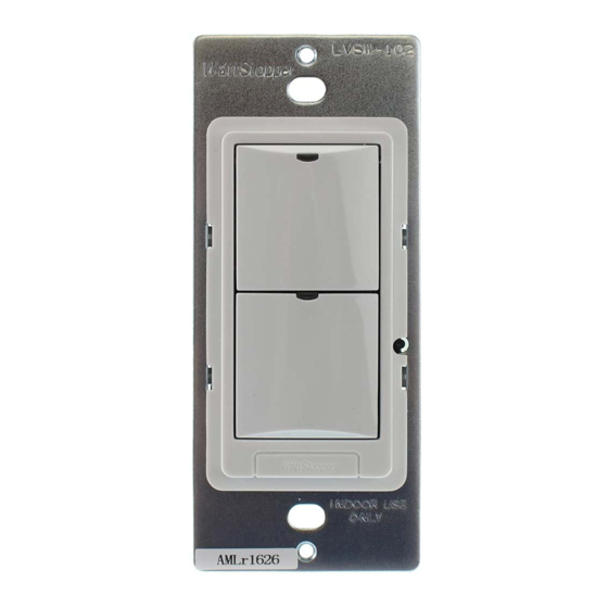
BUTTONS AND INDICATORS
DLM Local Network, regardless of their position on the DLM
Local Network.
Loads
1
2
Yellow wire
to Load B (2)
Digital Lighting Management
Low Voltage Switches
LMSW-104
Blue LED(s)
On/Off Button(s)
Configuration Button
(behind switch plate)
Red LED
DLM Local Network
(low voltage, Class 2)
LMRJ Cables
Corner Mount
Occupancy
Sensor
Room
Controller
J Box
To
Load/Line
(Class 1 wiring)
Switch
LMSW-108
Advertisement
Table of Contents

Related Manuals for wattstopper LMSW-102


Summary of Contents for wattstopper LMSW-102
- Page 1 Low Voltage Switches THESE UNITS ARE PRE-SET FOR PLUG n’ GO OPERATION, ADJUSTMENT IS OPTIONAL. LMSW-101 LMSW-102 LMSW-103 LMSW-104 LMSW-108 For full operational details, adjustment and more Voltage ................24VDC Current Consumption ............5mA features of the product, see the DLM System www.wattstopper.com...
- Page 2 Loads LMRC-102 Line Voltage The DLM Local Network is now in PnL mode. The Red LMSW-102 Room Controller Dual Relay LEDs continue to blink until you exit PnL mode. All loads in the room turn OFF after entering PnL. After one second, one load turns ON.
- Page 3 ADDITIONAL FILE FORMATTING, PLEASE CONTACT Mary Jo Sowinski. SANTA CLARA, CALIFORNIA Phone: 408-486-7511 MARCOM Email: maryjo.sowinski@wattstopper.com Title: LMSW-10x Quick Start Guide ENGINEERING All information in this drawing is the property of Watt Stopper and cannot be copied or used without the written approval of Watt Stopper.
Need help?
Do you have a question about the LMSW-102 and is the answer not in the manual?
Questions and answers