Advertisement
SPECIFICATIONS
Voltages . . . . . . . . . . . . . . . . . . . . . . . 24VAC, 24VDC, VAC Half Rectified
Current Consumption. . . . . . . . . . . . . . . . . . . . . . . . . . . . Max. 15mA DC
. . . . . . . . . . . . . . . . . . . . . . . . . . . . . . . . . . . . . . . . Max. 15mA AC
Outputs
Isolated Relay. . . . . . . . . . . . . . . . . . . . . . . . . . . . . . . . 1A/30V SPDT
Pulse On/Off:
Width. . . . . . . . . . . . . . . . . . . . . . . . . . . . . . . . . . . . . . .150ms
Current. . . . . . . . . . . . . . . . . . . . . . . . . . . . . . . . . . . . . . .1.5A
Time-Out Adjustment . . . . . . . . . . . . . . . . . . . . . . 5 minutes to 12 hours
Time-Out Override . . . . . . . . . . . . . . .0 to 1 hour in 5 minute increments
. . . . . . . . . . . . . . . . . . . 1 hour to 12 hours in 15 minute increments
Operating Temperature. . . . . . . . . . . . . . . . . . . 32° to 104°F (0° to 40°C)
Humidity . . . . . . . . . . . . . . . . . . . . . . . . . Rh 5% to 95%, non-condensing
TS-400-24
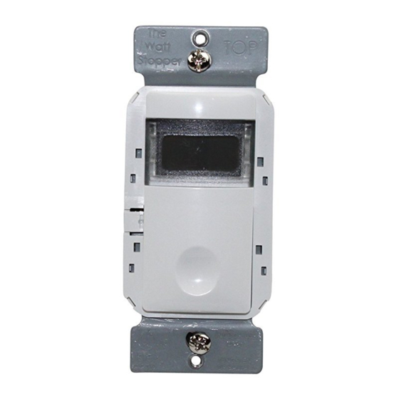
InteliSwitch ® Digital Time Switch
24VDC/VAC
U.S. Patent: 5,640,113
Advertisement
Table of Contents

Related Manuals for wattstopper intelliswitch TS-400-24


Summary of Contents for wattstopper intelliswitch TS-400-24
- Page 1 TS-400-24 InteliSwitch ® Digital Time Switch 24VDC/VAC SPECIFICATIONS Voltages ..... . . 24VAC, 24VDC, VAC Half Rectified Current Consumption......Max. 15mA DC ........Max. 15mA AC Outputs Isolated Relay....... . 1A/30V SPDT Pulse On/Off: Width........150ms Current........1.5A Time-Out Adjustment .
- Page 2 UNIT DESCRIPTION AND OPERATION The InteliSwitch ® TS-400-24 is a digital time switch that automatically turns lights off after a preset amount of time. The lights can also be turned off anytime during the timer’s countdown by pushing the ON/OFF button. The Digital Time Switch has four user-adjustable features: time-out period, time scroll direction, time-out visual and audible warnings. Time-Out Period The timer can be adjusted to hold lights on for five minutes to 12 hours. The default setting is 3 hours. See the DELAY switch adjustment to set the length of the time-out period. Time Scrolling The user can manually and temporarily override the time-out period without changing the DELAY adjustment. The SCROLL adjustment determines whether the user’s override options decrease from a longer time to a shorter time (scroll down) or increase from a shorter time to a longer time (scroll up). To choose the scrolling direction, consider the time-out DELAY setting, and then whether the usual temporary need will be for more or less time. Override Operation: Holding the ON/OFF button for longer than 4 seconds causes the timer to scroll through time increments, starting from the time-out DELAY setting. Releasing the ON/OFF button resumes the countdown from that point. The minimum override setting is 5 minutes, maximum 12 hours. The timer resets automatically to the time-out DELAY setting when the countdown runs out or the ON/OFF button is pushed. Visual (Flash) Option If this option is on there are two occasions when the controlled lights flash.
- Page 3 INSTALLATION CAUTION: TURN THE POWER OFF AT THE CIRCUIT BREAKER BEFORE WIRING. 1. Connect the existing wires to the TS-400-24 terminals. For Power Pack wiring: • +24VDC supply to +24V IN • +Supply COmmon to COMM Isolated Relay uses N.O. , N.C, and RLY COMM terminals. For Control Panel wiring: • +24VAC or +24VDC supply (BLU) to +24V IN • +Supply Common (WHT) to COMM. • On (RED) to PULSE ON • Off (BLK) to PULSE OFF 2. M ount the switch in the wall box with 2 mounting screws provided. 3. T urn on power to the time switch 4. 5 -10 seconds after power is supplied to the time switch, it will be ready to function.
- Page 4 WIRING #16-#18 Insert wires as shown and tighten screw in the clock- wise direction. SWITCH ADJUSTMENT Enter Settings Mode by pressing the Calibration Button (located on the left, behind the faceplate). LCD Display • I f no input occurs within four seconds the display flashes then moves to the next setting. • Press the Calibration Button to view the settings without making changes. Calibration Button • Press the ON/OFF button within four seconds to change the setting. ON/OFF DELAY: 5 min.
- Page 5 TROUBLESHOOTING CAUTION TURN OFF THE POWER AT THE CIRCUIT BREAKER BEFORE WORKING WITH HIGH VOLTAGE Lights will not turn on: 1. Verify that the ground wire is tightly secured. 2. If lights still do not go on, call 800.879.8585 for technical support. Lights will not turn off: 1.
- Page 6 ORDERING INFORMATION TS-400-24 Digital Time Switch 24VDC/24VAC, 60HZ ASP-211 Cover plate for single-gang box ASP-422 Cover plate for double-gang box ASP-432 Cover plate for double-gang box with switch option TS-400 and cover plates are available in White (-W), Light Almond (-A), Grey (-G), Black (-B), and Ivory (-I). Cover plates are not included. WARRANTY INFORMATION WattStopper warranties its products to be free of defects in materials and workmanship for a period of five years. There are no obligations or liabilities on the part of WattStopper for consequential damages arising out of or in connection with the use or performance of this product or other indirect damages with respect to loss of property, revenue, or profit, or cost of removal, installation or reinstallation. 2800 De La Cruz Boulevard, Santa Clara, CA 95050 800.879.8585 • www.wattstopper.com 02585 r3 05/12...
Need help?
Do you have a question about the intelliswitch TS-400-24 and is the answer not in the manual?
Questions and answers