Table of Contents
Advertisement
Quick Links
1. INTRODUCTION
This manual provides instructions and procedures necessary to install,
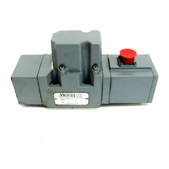
operate and troubleshoot the Moog 641 Series Proportional Control Valve.
Troubleshooting instructions are outlined so that the specific component(s)
suspected of failure can be identified.
2. OPERATION
The Moog 641 Series proportional control valves are suitable for open
and closed loop position and velocity control systems where accelerations need
to be regulated.The 641 can be used like a directional solenoid valve or a
proportional valve while controlling ram or motor acceleration, deceleration
and velocity.
The 641 Series valves are two-stage devices consisting of a double nozzle-
flapper pilot stage and a sliding spool main stage.The position of the main stage
spool is measured by a non-contacting position transducer. On-board integrated
electronics provide closed-loop position control of the main stage spool.
The operation of the 641 Series valve is controlled by an electrical
command signal (VQS) provided to the integrated control electronics which
drives the pilot stage coils.The current sent from the electronics causes the
flapper to move toward one nozzle, diverting the pilot stage flow to one end of
the spool.The position transducer measures the position of the spool (VLI) and
produces a feedback voltage which is directed back to the control amplifier and
compared to the command voltage.The control amplifier then drives the pilot
stage until the command voltage and feedback voltage are equal, centering the
flapper between the nozzles which holds the spool at a position proportional to
the command signal.
CAUTION
DISASSEMBLY, MAINTENANCE, OR REPAIR OTHER THAN IN ACCORDANCE WITH THE
INSTRUCTIONS HEREIN OR OTHER SPECIFIC WRITTEN DIRECTIONS FROM MOOG WILL
INVALIDATE MOOG'S OBLIGATIONS UNDER ITS WARRANTY.
m
641 Series Installation and
Operation Instruction
Proportional Control Valve
ELECTROHYDRAULIC VALVE CUT-AWAY
SINGLE STAGE
PILOT VALVE
SPOOL
P
A
T
B
MAIN STAGE
INLET ORIFICE
Figure 1 Moog Series 641
FLAPPER
V
QS
POSITION
CONTROL
NOZZLE
AMPLIFIER
V
LI
SPOOL POSITION
OSCILLATOR-
TRANSDUCER
DEMODULATOR
(LVDT)
Advertisement
Table of Contents

Summary of Contents for Moog 641 Series
- Page 1 The 641 Series valves are two-stage devices consisting of a double nozzle- flapper pilot stage and a sliding spool main stage.The position of the main stage spool is measured by a non-contacting position transducer. On-board integrated electronics provide closed-loop position control of the main stage spool.
- Page 2 Base O-Rings 42082-11 Filter O-Ring (1) G2140-13-15 The Moog 641 Series Proportional Control Valves may be mounted in any position, provided the valve pressure, control, and return ports match respective Filter Retainer Plate O-Ring (1) G2140-17-20 manifold ports.The mounting pattern and port location of the valve are shown...
- Page 3 8. FILTER ASSEMBLY REPLACEMENT 10.AUTHORIZED REPAIR FACILITIES Moog does not authorize any facilities other than Moog or Moog subsidiaries to Using a 3 mm Allen wrench, remove the four (4) socket head capscrews repair its servovalves. It is recommended you contact Moog at (716)655-3000 and lockwashers.
- Page 4 641 SERIES INSTALLATION AND OPERATION INSTRUCTION NOTES 1 Fluid: 8.74 MAX Industrial type petroleum base hydraulic [222.0] 2.75 MAX fluid, maintained to ISO DIS 4406 Code [69.9] 14/11 recommended. 2.126 [54.00] 2 Operating Temperature Range: 3.85 1.063 ELECTRICAL [97.8] [27.00] -4˚F to 175˚F (-20˚C to 80˚C)


Need help?
Do you have a question about the 641 Series and is the answer not in the manual?
Questions and answers