Advertisement
Quick Links
1. INTRODUCTION
This manual provides instructions and procedures necessary to install,
operate and troubleshoot the Moog Series 631K/D631K series intrinsic safety
protected Industrial Serovalve. Troubleshooting instructions are outlined to
permit the identification of the specific component(s) suspected of failure.
The 631K/D631K series valves are electrical equipment for hazardous areas
with intrinsic safety protection. Identification
CESI 02ATEX109 X,
nnnn (see product label, Ex. 0344). They are intended
for directional, position, velocity, pressure and force control in hydraulic control
systems that operate with mineral oil based fluids. Others upon request.
2. OPERATION
The Moog 631K/D631K Series Industrial Servovalve consists of a polarized
electrical torque motor and two stages of hydraulic power amplification. The
motor armature extends into the air gaps of the magnetic flux circuit and is
supported in this position by a flexure tube member. The flexure tube acts as a
seal between the electromagnetic and hydraulic sections of the valve. The two
motor coils surround the armature, one on each side of the flexure tube.
The flapper of the first stage hydraulic amplifier is rigidly attached to the
midpoint of the armature. The flapper extends through the flexure tube and
passes between two nozzles, creating two variable orifices between the nozzle
tips and the flapper. The pressure controlled by the flapper and nozzle variable
orifice is fed to the end areas of the second stage spool.
The second stage is a conventional 4-way spool design in which output
flow from the valve, at a fixed valve pressure drop, is proportional to spool
displacement from the null position. A cantilever feedback spring is fixed to
the flapper and engages a hole at the center of the spool. Displacement of the
spool deflects the feedback spring which creates a force on the armature/flapper
assembly.
Input signal induces a magnetic charge in the armature and causes a
deflection of the armature and flapper. This assembly pivots about the flexure
tube, and increases the size of one nozzle orifice and decreases the size of the
other.
This action creates a differential pressure from one end of the spool to
the other and results in spool displacement. The spool displacement transmits
a force to the feedback wire which opposes the original input signal torque.
CAUTION
DISASSEMBLY, MAINTENANCE, OR REPAIR OTHER THAN IN ACCORDANCE WITH THE
INSTRUCTIONS HEREIN OR OTHER SPECIFIC WRITTEN DIRECTIONS FROM MOOG WILL
INVALIDATE MOOG'S OBLIGATIONS UNDER ITS WARRANTY AND INTRINSICALLY SAFE
PROTECTION PERMIT NULL AND VOID.
II 1G Ex ia IIC T6 or T5 Ga
ELECTROHYDRAULIC VALVE CUT-AWAY
631K/D631K Series Installation
and Operation Instruction
Electrohydraulic Servovalve
Intrinsic Safety Protected
Null Access
Screw
Null Adjust
Torque Motor
Coil
Armature
Flexure Tube
Filter
X T
A
P
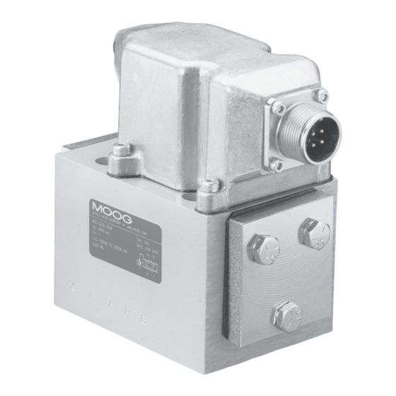
Figure 1 Moog Series 631K/D631K
Upper Polepiece
Flapper
Nozzle
Feedback Wire
Spool
Inlet Orifice
Filter Plate
(not shown)
B
Advertisement

Related Manuals for Moog 631K Series


Summary of Contents for Moog 631K Series
- Page 1 1. INTRODUCTION This manual provides instructions and procedures necessary to install, and Operation Instruction operate and troubleshoot the Moog Series 631K/D631K series intrinsic safety protected Industrial Serovalve. Troubleshooting instructions are outlined to Electrohydraulic Servovalve permit the identification of the specific component(s) suspected of failure.
- Page 2 6. INSTALLATION SAFE CIRCUIT SAFETY PARAMETERS The Moog 631K/D631K Series Servovalves may be mounted in any position, a. The electrical torque motor coil leads are attached to the valve connector provided the servovalve pressure, control and return ports match respective so external connections can provide series, parallel or single coil manifold ports.
- Page 3 11. AUTHORIZED REPAIR FACILITIES Moog does not authorize any facilities other than Moog or Moog subsidiaries to repair its servovalves. It is recommended you contact Moog at (716) 652- 2000 to locate your closest Moog repair facility. Repair by an independent (unauthorized) repair house will result in voiding the Moog warranty and could lead to performance degradation or safety problems.
- Page 4 External X open closed Moog Inc., East Aurora, NY 14052-0018 Telephone: 716/652-2000 Fax: 716/687-7910 Toll Free: 1-800-272-MOOG The products described herein are subject to change at any time without notice, including, but not limited to, product features, specifications, and designs.
Need help?
Do you have a question about the 631K Series and is the answer not in the manual?
Questions and answers