Table of Contents
Advertisement
Quick Links
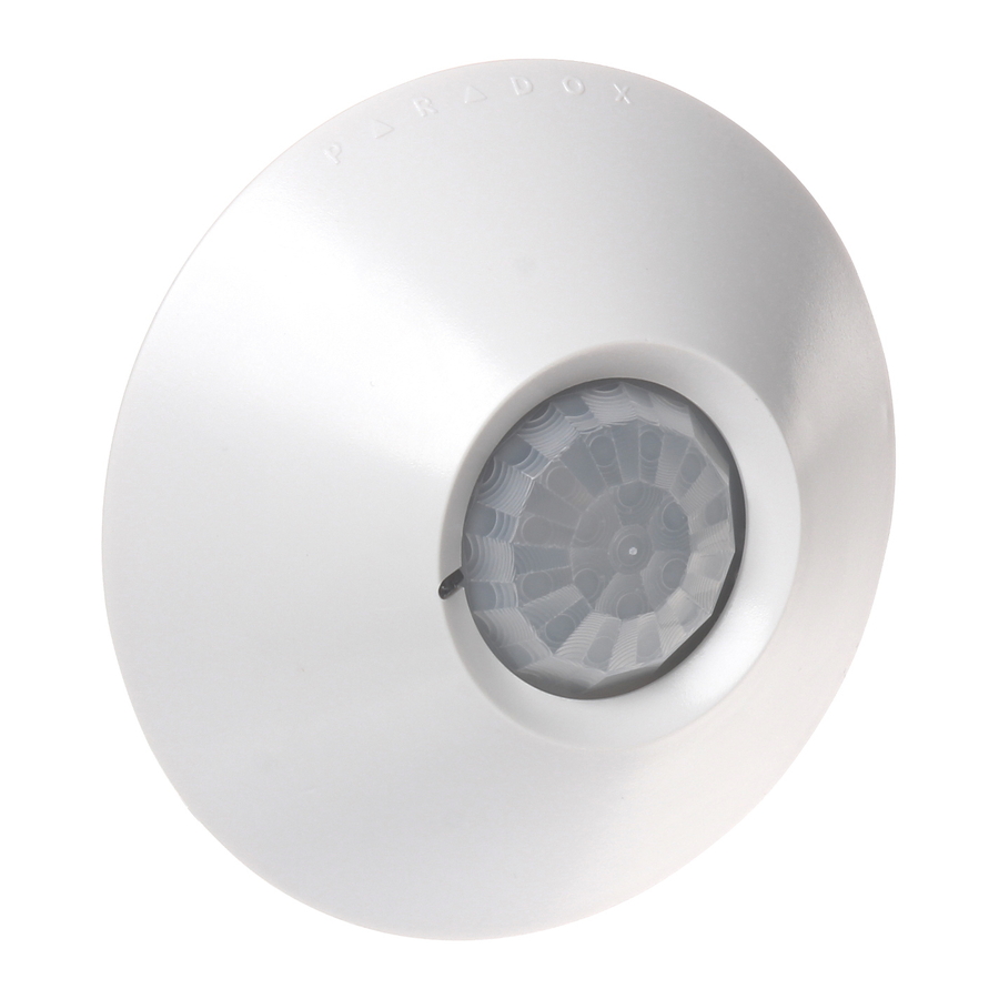
Ceiling-Mount Digital Motion Detector
Instructions / Instrucciones
Printed in Canada 4/2007
paradox.com DG467-TI00
Installation
Select the detector installation site, usually in the center of the protected area.
Please note that coverage area is more elliptical than circular (see figure 2).
Avoid proximity to any of the following: reflective surfaces; direct air flow from
vents, fans and windows; sources of steam/oil vapor; objects causing
temperature changes such as heaters, refrigerators and ovens; and infrared light
sources.
The DG467 provides ATC (Automatic Temperature Compensation) but it
is still highly recommended to retest unit coverage with a walk-test if
temperatures reach over 30°C (85°F). This is extremely important in non-
ventilated areas.
To Install the DG467:
1. Remove the PCB screw, then carefully remove the PCB (see figure 3).
2. Drill screw / wire holes (see figure 3).
3. Run the wires through entry holes and connect them according to the PCB
markings (see figure 1).
Opening and Closing the Cover (see figure 3)
To replace the lens:
Gently push the lens and bezel out of the cover.
To reinstall the lens:
Align the bezel pin with the matching hole in the lens
and cover.
To close the detector: Align the arrow in the cover with the arrow on the PCB
and turn the cover clockwise.
Do not touch the sensor surface as this could result in detector
malfunction. If necessary, clean with a soft cloth and pure alcohol.
Operational Modes
The DG467 can function in two different operational modes: combus mode or
relay mode. This option can only be configured using the J4 jumper.
Relay Mode: (J4 = OFF)
When set to Relay Mode, the DG467 functions as would any standard
motion detector by communicating its alarm and tamper signals via relays.
The GRN and YEL terminals are not used in relay mode. In Relay Mode,
the detector's settings can only be modified using the jumpers (see figure
1).
Combus Mode: (J4 = ON)
When set to combus mode, the DG467 communicates alarm signals,
tamper signals, data and detector settings via the panel's 4-wire combus.
The detector's relay output always remains active even when set to
combus mode and can be used to activate other devices.
In combus mode, the motion detector can be modified using the jumpers or
by entering module programming mode.
In combus mode, the DG467 will respect the most recent
modification whether it is made through the jumpers or through
section programming. As a result, current jumper positions may not
represent actual settings. All settings are stored in the DG467 even
after it has been powered down.
Detector Settings
Section /
Step
Details
Jumper
1
J4 OFF =Relay mode
(go to step 3)
Operational
J4
J4 ON =Combus mode (go to step 2)
Mode
Enter detector programming mode.
2
Press and hold [0] + [
] + [4003] (EVO) or
INSTALLER CODE
[953] (DGP-848) + SN.
Single edge processing should be used in normal
environments with minimal sources of interference. Dual
Edge Processing provides better false alarm rejection if
the detector is placed near sources of interference that
3
can adversely affect it.
Signal
Processing
[1] OFF =Dual edge
Mode
[1] ON =Single edge
[001]
or
or
J3
J3 OFF =Dual edge
J3 ON =Single edge
LED flash = Movement without alarm (see step 5)
LED on 5 sec. = Movement with alarm
4
[2] OFF =LED disabled
LED
[2] ON =LED enabled
[001]
Settings
or
or
J1
J1 OFF =LED disabled
J1 ON =LED enabled
Detects movement signals that do not reach the required
energy levels for an alarm. The LED flashes once,
5
indicating the signal was kept in memory.
Movement
Note: The LED must be enabled. (see step 4)
Without
Alarm
[3] OFF =Movement Without Alarm disabled
[001]
[3] ON =Movement Without Alarm enabled
Note: In relay mode, this feature is always enabled.
The detector can send a tamper signal to the control
6
panel via the combus.
Tamper
[5] OFF =Tamper recognition disabled
Recognition
[001]
[5] ON =Tamper recognition enabled
In High Shield mode, the detector is set for high-risk
environments (potential interferences) and therefore
provides greatly increased false alarm immunity.
However, response time and detector speed may be
slower.
7
000
=Very low shield (very high sensitivity)
Digital
[002]
001
=Low shield (high sensitivity)
Shield
002
=Normal shield (normal sensitivity)
or
003
=High shield (low sensitivity)
or
J2 OFF =High shield
J2
J2 ON =Very low shield
= default settings
Utilities
Used for trouble-shooting, the voltage meter Indicates
the DG467's input voltage.
Voltage
Displays [3-digit number] which represents input
Meter
[900]
voltage x 10
e.g. [133] = 13.3V
Powering The DG467
Self-testing program: Turning on the detector initiates a self-testing program for
the signal processor, memory and relay. The LED flashes rapidly for
approximately 4 seconds. The detector then switches to "stand-by" mode.
Walk-testing
At 20°C (68°F) you should not be able to cross more than one complete zone
(consisting of 2 beams, left and right sensor detecting elements) in the coverage
area with any kind of movement. When using a higher level digital shield
settings, the amount of movement required to generate an alarm is increased.
When conducting a walk test, move slowly in order to generate weak signals. Try
to move to the maximum coverage distance. An alarm is indicated by a constant
light for 5 seconds.
Motion detectors should be walk-tested annually.
Figure / Figura 1
To close unit, align
Anti-tamper switch
PCB arrow with
Antisabotaje interruptor
cover arrow
interrupteur de sécurité
Para cerrar la
Power input 12Vdc
unidad, alinear la
Alimentación 12Vdc
flecha de la PCI con
alimentation de 12 Vc.c.
la flecha de la
cubierta.
Combus (J4 ON)
Pour fermer l'unité,
Combus (J4 ON)
aligner la flèche de
combus (J4 ACTIVÉ)
la carte de circuits
imprimés avec celle
Alarm relay
du couvercle
Relé de alarma
relais d'alarme
Figure / Figura 2
-all measurements
0
shown in meters
and (feet)
-todas las medidas
están en metros
y (pies)
2.4
-toutes les
(8) 4.0
3.0
1.5
0
1.5
3.0
4.0
mesures sont
(12)
(10)
(5)
(5)
(10)
(12)
indiquées en
mètres et en
(pieds)
3.0
(10)
LED
0
0
3.0
(10)
4.0
0
4.0
(12)
(12)
Figure / Figura 3
1
Bezel
Bisel
monture
1
2
Align arrows
Alinear flechas
flèches d'alignement
2
3
PCB screw
Tornillo de PCI
vis de la carte de circuits
3
imprimés
4
Screw / wire entry holes
Tornillo / cable
agujeros de entrada
trous d'entrée pour les
vis / fils
4
Technical Specifications
Sensor type:
Dual Opposed Element Infrared
Sensor geometry:
Rectangular
Detection speed:
0.2m/s to 3.5m/s (0.6ft/s to 11.5ft/s)
Coverage:
360°, 7m X 6m (24ft X 20ft) at a height of 2.4m (8ft)
360°, 11m X 6m (35ft X 20ft) at a height of 3.7m (12ft)
Installation height:
2.1m to 4m (7ft to 12ft)*
Operating temperature:
-20°C to +50°C (-4°F to +122°F)
Power input:
9 to 16Vdc, 29mA maximum at 12V
Lens:
LODIFF® segment Fresnel ceiling mount array
EMI / RFI rejection:
10V/m
Alarm output:
N.C. 28Vdc, 0.15A / via combus
Anti-tamper output
N.C. 0.15A, 38Vdc, opens when cover is removed / via combus
Size
10.8cm dia. X 3.5cm height (4.25" X 1.38" height)
Compatibility
Combus Mode
All Digiplex series (DGP/DGPNE) and all EVO series
control panels.
Relay Mode
All major security system manufacturers
* Can be installed as high as 4.5m (14ft), however sensitivity will be compromised.
Español
Instalación
Elegir el lugar de instalación del detector, de costumbre al centro del área
protegida. Tomar en cuenta que el área de cobertura es más elíptica que circular
(ver la figure 2). Evitar ubicarlo cerca de las siguientes fuentes de interferencia:
superficies reflectantes; corrientes de aire provenientes de sistemas de
ventilación, ventiladores y ventanas; fuentes de vapor de agua / humo de aceite;
objetos que provoquen cambios de temperatura como aparatos de calefacción,
refrigeradores y hornos; y fuentes de luces infrarrojas.
El DG467 provee Compensación Automática de Temperatura pero se
recomienda enfáticamente probar la cobertura de la unidad mediante una
prueba caminando si la temperatura llega a 30°C (85°F) o más. Esto es
de extrema importancia en áreas sin ventilación.
Para Instalar el DG467:
1. Retirar el tornillo de la PCI, y después retirar cuidadosamente la PCI (ver la
figure 3).
2. Hacer agujeros para tornillos / cables (ver la figure 3).
3. Pasar los cables por los agujeros de entrada y conectarlos de acuerdo a las
marcas de la PCI (ver la figure 1).
Abrir y Cerrar la Cubierta (ver la figura 3 en pág. 1)
Para abrir el detector:
Girar la cubierta de derecha a izquierda.
Para remplazar el lente:
Empujar suavemente los lentes y el bisel afuera de la
cubierta.
Para reinstalar el lente:
Alinear el pin del bisel con el agujero en el lente
cubierta.
Para cerrar el detector:
Alinear la flecha en la cubierta con la flecha en la PCI.
girar la cubierta de izquierda a derecha.
No tocar la superficie del sensor pues puede provocar el mal
funcionamiento del detector. De ser necesario, limpiar con un paño
delicado y alcohol puro.
Modos de Funcionamiento
El DG467 puede funcionar en dos modos diferentes de funcionamiento: modo
combus o modo relé. Esta opción sólo puede ser configurada con el puente J4.
Modo Relé: (J4 = OFF)
Al estar configurado en Modo Relé, el DG467 funciona como un detector
de movimiento estándar comunicando sus señales de alarma y de
sabotaje mediante los relés. Los terminales GRN y YEL no son usados en
el modo relé. En el Modo Relé, la configuración del detector sólo puede
ser modificada mediante los puentes (ver la figura 1).
Modo Combus: (J4 = ON)
Al estar configurado en Modo Combus, el DG467 comunica las señales de
alarma, de sabotaje, los datos y la configuración del detector mediante el
combus de 4 cables de la central. La salida de relé del detector siempre
permanece activa incluso cuando está configurada en modo combus y
pude ser usada para activar otros dispositivos.
En el modo combus, el detector de movimiento puede ser modificado
mediante los puentes o accediendo al modo de programación de módulo.
En el modo combus, el DG467 responde a la más reciente
modificación efectuada mediante los puentes o mediante la
programación de secciones. En consecuencia, las posiciones
actuales de los puentes podrían no corresponder a la configuración
en curso. Todas las configuraciones permanecen almacenadas en
el DG467 incluso después de haberlo apagado.
Configuración del Detector
Sección
Paso
Detalles
/ Puente
1
J4 OFF =Modo Relé
(ir al paso 3)
Modo de
J4
J4 ON
=Modo Combus (ir al paso 2)
Funcionamiento
Ingresar al modo de programación de detector:
2
Pulsar y mantener [0] + [
CÓDIGO DE INSTALADOR
[4003] (EVO) ó [953] (DGP-848) + NS.
] +
Advertisement
Table of Contents

Subscribe to Our Youtube Channel
Related Manuals for Paradox Paradome DG467


Summary of Contents for Paradox Paradome DG467
- Page 1 áreas sin ventilación. can adversely affect it. Signal Printed in Canada 4/2007 paradox.com DG467-TI00 Processing [1] OFF =Dual edge Para Instalar el DG467: Mode Figure / Figura 2...
- Page 2 Systèmes de sécurité Paradox Ltée (« Vendeur ») garantit, pour une période d’un an, que ses produits ne comportent aucun défaut de pièce ou de main-d’oeuvre =Blindaje normal (sensibilidad normal) si utilisés dans des conditions normales. Sauf ce qui est expressément prévu par les présentes, toute autre garantie, expresse ou implicite, légale ou autre, sans Pour remettre en place la lentille : Aligner la broche de la monture dans les trous ó...
Need help?
Do you have a question about the Paradome DG467 and is the answer not in the manual?
Questions and answers