Advertisement
Quick Links
DESCRIPTION
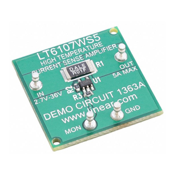
Demonstration circuit 1363 is a General Purpose High-
Side Current-Sense Ampl if ier f eaturing the LT6107.
This demo board ampl if ies an on-board current-sense
resistor vol tage-drop, providing a precision uni-pol ar
output vol tage proportional to l oad current. The demo
circuit incl udes scal ing resistors that program the gain of
the circuit to 50V/ V. The LT6107 is pow ered f rom the
same suppl y that the sense resistor is connected to and
provides a ground ref erenced output. The LT6107 can
perf orm current measurements on suppl ies ranging f rom
2. 7V to 36V. Since the output vol tage is devel oped as a
control l ed current through a l oad resistance, ground-
l oop errors can be el iminated by simpl y l ocating the l oad
resistor at the destination point (subsequent signal
PERF ORM ANCE SU M M ARY
SYM BOL
PARAM ETER
V
M onitored Suppl y Input Range
IN
V
M easurement Output Signal
M ON
I
M easurement Output Signal (current mode)
M ON
I
Output Load Current Range
OUT
I
V
Quiescent Current
INQ
IN
t
V
step-response time
R
M ON
OPERATING PRINCIPL ES
The LT6107 operates by ampl if ying the vol tage drop on a
sense resistor pl aced in series w ith the pow er source of a
l oad to be monitored. The sense inputs of the ampl if ier
dif f erential l y measure the sense-resistor drop to control
an internal variabl e current source that al l ow s transl ation
of the input inf ormation to a l evel ref erenced to V–
(ground in this demo circuit). The circuit gain is
establ ished by the ratio of the output resistor to the input
H ig h Te m p e ra tu re H ig h S id e
Cu rre n t S e n s e in a S OT-2 3
processing such as A/ D conversion). Remote l oading can
be eval uated by simpl y removing the on board l oad
resistor (R3).
DC1363 is f abricated f rom FR-406 high-temp epoxy-
gl ass so that the f ul l 150° operation of the LT6107 can
be demonstrated. Other key perf ormance characteristics
of the LT6107 and DC1363 are show n in the
Perf ormance Summary bel ow .
Design files for this circuit board are available. Call
the LTC factory.
L
, LT are registered trademarks of Linear Technol ogy Corporation. Other product names
may be trademarks of the companies that manuf acture the products.
Specifications are at T
= 25°C
A
CONDI TI ONS
I
= 5A
OUT
I
= 5A, R3 removed
OUT
Thermal l imit of R
SENSE
V
=12V, I
= 0A
IN
OUT
I
step f rom 0A to 5A
OUT
resistor and is essential l y as accurate as the resistors
used. In DC1363 as shipped, the sense resistor instal l ed
is 10mΩ and the resistor ratio sets the gain to 50V/ V, so
the nominal output scal ing is 500mV per Ampere of l oad
current. Other scal ings can be produced by resistor
repl acement on the demo circuit.
The DC1363 Schematic diagram is show n in Figure 2.
DEMO CIRCUIT 1 3 6 3
Q UICK S TA RT G UIDE
M I N
TYP
2. 7
3... 28
2. 5
500
65
5
LT6107
L T6 1 0 7
M AX
UNI TS
36
V
V
µA
5
A
µA
µs
1
Advertisement

Related Manuals for Linear Technology LT6107


Summary of Contents for Linear Technology LT6107
- Page 1 DC1363 is f abricated f rom FR-406 high-temp epoxy- output vol tage proportional to l oad current. The demo gl ass so that the f ul l 150° operation of the LT6107 can circuit incl udes scal ing resistors that program the gain of be demonstrated.
- Page 2 Demonstration circuit 1363 is easy to set up to eval uate 2. Connect a vol tmeter or oscil l oscope probe to the M ON the perf ormance of the LT6107. Ref er to Figure 1 f or terminal , w ith the common connection or ground cl ip proper measurement equipment setup and f ol l ow the tied to GND.
- Page 3 LT6107 Figure 2. DC1363 Schem atic Diagram...
Need help?
Do you have a question about the LT6107 and is the answer not in the manual?
Questions and answers